Version 9 or 10 with Hardware Clock
Following numerous requests for a hardware clock to be included I have made use of the DS1307 board from Futurlec. There is nothing complex about it and one could easily be manufactured for yourself. I have attached the circuit. The Futurlec board is quite inexpensive and works well. The difference between V9 and V10 is the use of a 4 line * 80 character display for the V9 series.
I have taken the opportunity to work on a couple of other areas. these include changes to the averaging facility to enable averaging while the antennas are both moving and stationary, support for the Yaesu GS232A rotator interface, and improvement to the antenna update speed when using Mode B relays. There are no hardware changes apart from the addition of the DS1307 hardware clock and the removal of the 32KHz crystal and its capacitors. There is additional information in the manual and a couple of error fixes.
A new command has been added. It is called "RunOn" and is used to allow for the run on that occurs with many rotators when the power is removed after movement. This is a variable that can be operator configured (menu items 39,40) to allow for run on and adds to the 'Hysteresis" function that also endeavours to deal with this problem. The idea is that when using "Auto" the antenna is moved as closely as possible to the correct heading and then does not move until the object moves outside the hysteresis limits at which point it moves back to the centre. By adding "RunOn" the system will stop short of the desired azimuth or elevation to allow for the antenna running on to the centre. This mod is in Version 9.03.
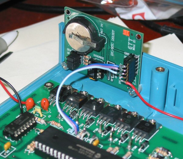
Futurlec's DS1307 hardware clock wired into board in place of 32KHz crystal.
See the Version 9
manual for details on the connections.
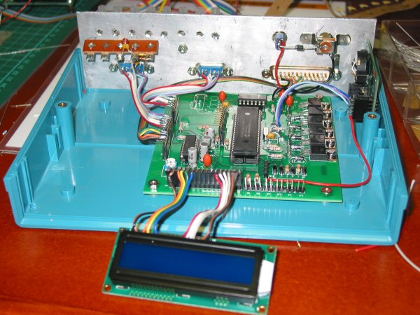
Shows some aspects of the construction and wiring
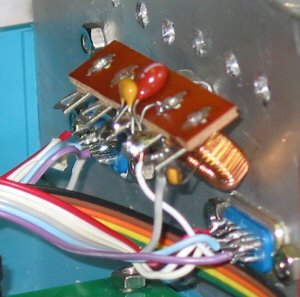
When using potentiometer input it may be necessary to add an RF filter.
Mine consists of a small ferrite ring wound with 30 or so turns with 10nF
and 10uF bypasses on input and output. It is mounted at the DB9.
In the photo the filter is installed on the azimuth DB9.
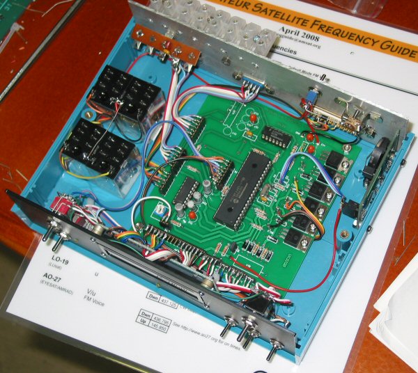
Top view showing general layout.
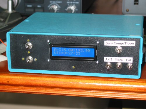
Modified switch arrangement with multiple position switches.
Left of LCD: Up/Down and Left/Right are centre off, spring
loaded two way.
Right of LCD: Sun/computer/moon
switch has used a two pole, centre off, two position switch to combine
the
external/internal switch and the sun/moon switch. Positions are 'up'
for sun, 'centre' position is external computer control
and 'down' is moon.
This arrangement could have been done with two separate switches as per the original
design.
At lower right are the three switches for Auto/Manual (on for manual), menu
(on for menu), calibrate (on to calibrate)
Version
10.00 Documentation and Hex file for 18F4682 or 18F4685 on 10 June
2010
(I have not been able to test the
Yaesu GS232A function as I don't have one. Can anyone help?.There is a questions
whether I have to provide a <CR> at the end of each string. Currently I
do not.)
I've written the 9.51 version for a 4 line display. Two LCDs have been trialled
(1) HDM40416L from Futurlec.
(2) LKC-4004 from lcdmodkit.com
I've used the extra two lines and the wider display to permanently display the UTC time and local time (offset is set in the menu), moon declination and display the doppler shift and the frequency when the moon is above the horizon. Because this LCD actually has two controllers on board I have had to use the unused DTR pin on the computer interface J1 (pin 4) to enable the second controller for the bottom 2 lines. If you are interested send me an email.
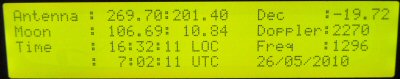
Disregard the awful photo but this gives an idea of the new display on test.
Note addition of Declination and permanent display of time
and Doppler Shift and Frequency (when moon above horizon)
I've also done some work on the alignment of the AZ and EL readings on the
LCD
![]()