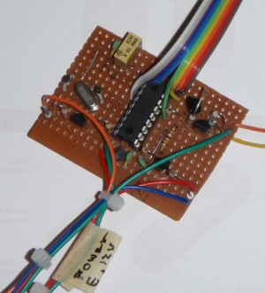
The matrix board prototype
A PIC based Quality Checker for GPS Frequency Lock Applications
Amateurs using digital modes of communication or those requiring high stability at UHF frequencies need a guarantee about frequency.
The matrix board prototype
One way of achieving this is to use a PLL system based on a GPS derived 10MHz signal. Due to the vagaries of weather and satellite availability, the signal from the satellites does vary and sometimes a perfect 3D lock is not available. It is critical that the operator knows when he/she has lost sync.
This project taps into the NMEA stream and provides both a visual display with an LCD and also LED indicators and a sounder.
The LCD outputs include "3D Lock", "2D Lock" and "NO Lock" while the UTC time is also displayed to screen.
Three digital outputs of the 16F628A provide switching though small NPN transistors to operate the indicator LEDs or sounder. A green LED is labelled "3DLock", an orange LED labelled "2D Lock" and a red LED and sounder are labelled "NO Lock".
The LCD output is to a single line LCD. The 16 character LCD I used is one of those that treats the single line as two lines of 8 characters. The first 8 characters are printed from 1,1 while the second half of the line is printed to 2,1 resulting in one line of 16 characters. It just requires a little more thought when constructing the print statements.
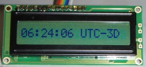
The LCD is shown indicating current UTC time with an indication that a
full
3D decode is taking place.
A 3D decode confirms that the 10 MHz output is GPS locked and reliable.
Here is a typical $GPGSA string showing quality as 3, it is the second item.
$GPGSA,A,3,04,05,,09,12,,,24,,,,,2.5,1.3,2.1*39
The quality data has a value from 1-3. A value of 1 indicates zero lock, a value of 2 implies a 2D condition (acceptable but not ideal) while a value of 3 implies a full 3D lock and therefore the best result available.Note that in the code I also allocate a value to ValueA. This byte variable is used to remove the first bit of data in the GSA string so that the PIC can access the second item which is the quality value. ValueA is never used.
Derivation of the time is obtained from the $GPGGA string and is the first item in the GGA list. In this example string it is 123519 which would be printed as 12:35:19.
$GPGGA,123519,4807.038,N,01131.000,E,1,08,0.9,545.4,M,46.9,M,,*47
Using the DEC modifier to allocate it to a DWORD variable this number is then worked on using modulus and integer divide to extract the seconds, minutes and hours. The print statement tests for values of less than 10 (one digit) and adds a zero if necessary to maintain the printed string length.
Most GPS are either locked to 4800 baud output or may be enabled for 4800 baud. The USART in the PIC is set for 4800 baud receive using asynchronous 8 data bits, no parity and 1 stop bit. Note that once the receive port has been set (PortB.1) the transmit port (PortB.2) is no longer available for general IO.
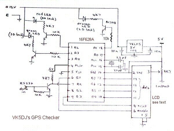
The PIC is a 16F628A while the transistors can be any general purpose NPN type. The crystal is 8MHz, although any frequency would work providing you match the crystal definition in the program source. The LCD at right must be an intelligent LCD module using the Hitachi 44780 controller (or compatible). If you buy a 2 line display LCD1 by Hantronics from Mini-Kits here in South Australia - he seems to have the best value displays - use the second version below.
If an operator wants an audible indication of loss of lock a piezo sounder could be connected between 12V and the collector of the transistor driving the RED LED.
If your GPS engine does not have a MAX232 (or 233) fitted and you have just the TTL output of the engine, modify the above circuit by removing all the parts associated with pin 7 (2 resistors and one transistor) and replace these with a single 10K resistor to the TTL output of the engine. This removes the polarity inversion and negative voltage protection provided by the transistor as this is no longer required.
Here is the hex code to program your PIC for use with a 1 line LCD display, some of you will have these 'specials' from places like Rockbys. They work fine and have larger characters.
Here is the hex code for a PIC driving a genuine 2 line LCD display for example from Mini-Kits. These have the advantage of being back lit.
Updating the system clock on your Windows Computer
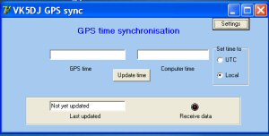
I wrote a simple program to update the computer's system clock from the GPS.
It works by using the GPS serial output and then selecting the options
in Settings
to configure the port. After that it remembers the settings if you are using
a real com port.
If you need to use a USB to serial converter you may find that the com port
number changes each time you restart the computer.
There is facility for doing an immediate update or allowing the program to
auto update your system clock every hour on the hour.