Downloads
Repeater
controller
16F628
(self extract)
Version 6.46
Repeater
controller
16F628
(ZIP)
Version 6.46
Controller
manual
(PDF)
Version 6.46
Using an 8870
by Arrio IW6BFE
Italian
language manual
Project description by Arrio IW6BFE
DTMF
expansion
Temporarily back on see note
General features include:
Two port linking repeater controller design for amateur or professional use - usually a duplex repeater on port 1 and a simplex link or gateway on port 2. As well as the conventional morse ID via a morse code callsign, the controller can also operate in beacon mode to deliver a short morse message at a programmable interval. All timers are remote configurable by DTMF as is the callsign and a CW message facility. CTCSS access is provided. The key to the project is the PIC16F628A microcontroller. The latest HEX file is available free from this site.
Click here for a summary of key features.
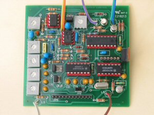
The main download is a set of document files, photos, GERBER files for board manufacture, hex file for loading the PIC and PDFs to assist readers in the building of a repeater controller.
General ERRATA
The original 16F84 repeater controller was the subject of an article in Amateur Radio Magazine October 2004. Since the article was submitted in October 2003, the controller has some important improvements, including the use of a 16F628 (or 16F648A) to provide more memory for extra features. (Requires a 1cm long link on bottom of board - see below). The original now obsolete 16F84 controller hex code is still available from this site (see obsolete downloads), but as the board modification consists of only one short (1cm) jumper on the back of the board it is highly recommended that you update to the new 16F628 version.
From Version 6.00 there are significant changes in the remote control scheme. More remote control functions were required so I have altered the remote system to a pattern where a 2 digit hex number is required for each address. In addition I have re-ordered instructions to enable some saving in space. This has been so successful that more features are now contained in less program space although there are 62 instead of 67 characters for the callsign and message. A downside is that care is now required in using remote functions 01, 02 and 03 as the options within each function must be sent as a whole, you might have to do some simple arithmetic using hex numbers. The manual explains the changes - read it carefully. On 20th October 2007, I corrected an error on page 8 regarding command 00. The correct parameter to inhibit timeouts is 03. The detailed description on P9 was correct. The document file has been updated.
From Version 6.22 there are now five ident options:
- Standard: end of transmission if timer expired, and then once when the repeater is unused and the timer expires.
- Three second mode: during repeater use same as Standard mode but in quiet times it requires a 3 second received signal before it will provide an ident (helps avoid problems caused by button pushers). A quiet period (value depends on the secondary tail value) must pass before another 3 second received carrier will start an ident.
- Swedish European: This mode idents at the start of transmissions if the call timer is expired, and during operation of the repeater whenever the timer expires. If secondary tail timer is activated (Function 01 10) it idents when the secondary timer shuts. The repeater then remains silent.
- Italian European: This mode idents whenever the callsign timer expires (beacon mode) but not if a signal is being received. If timer expires during use, it idents when the mute closes.
- No callsign: Introduced for those countries that do not require a callsign to be sent
In addition to the 5 ident options, the extended tail function (this timer is shared with 3second ident mode) used in European countries is now fully adjustable in seconds (max of 15 secs).
The 1750 HZ beep access mode is retained and this remains open even for non 1750 stations until the secondary tail closes. The extended tail and delayed mute must be set for 1750 operation
A new mode called 'Extended CTCSS' is available. This mode may be used when CTCSS is required for operation. If the 'CTCSSExtended Mode' is set then if one station opens the repeater with CTCSS the repeater remains 'open' until an adjustable timer expires or another CTCSS station accesses the system.
AC Fail is now available providing you are willing to make a small board change (cutting a track and adding a PCB pin to enable access). No board change is required if you don't need the AC Fail indication but note that it is ESSENTIAL from Version 6.10 to ensure that in your programmer the MCLR pin is DISABLED. I have modified the latest version 6.22 handbook to re-inforce this - Thanks for spotting the error in the handbook Fred, PA4YBR.
'Roger beep' or 'tail beep' is now available even when the link/gateway is inhibited. (However beeps may be commanded off)
Link/Gateway is now controlled by a stored value and survives a power off.
A facility to have no callsigns at all is added.
A facility to have remote controls from a completely separate receiver that does not require a COS input to the controller.
On power up a burst of PTT is now prevented and the controller comes on stream faster.
Version 6.33 fixes CTCSS timeout on secondary port, overcomes a potential lock up when using a link unit that hears its own signal and ADDS a facility to send a short pulse on the secondary port if it is unused for link/gateway operations. See command 00 04. This may be used to reset an external device.
Version 6.35 fixes a problem with DTMF operation from a separate receiver. It now works whether the unit is inactive, repeating a signal (or suffering interference) or even time out.
Version 6.36 fixes a problem with the external rcvr DTMF where audios were shut down during control functions
Version 6.37 fixes a bug in the CTCSS timeout function. It was not exitting smoothly after a timeout. Very minor change.
Version 6.38 made frequencies for beep and boop tones available in EEDATA for adjustment at program time
Version 6.39 enabled EITHER CTCSS reception OR COS opening to trigger the controller on repeater port.
Version 6.40 made the CTCSS anti-jitter value to be accessed in EEDATA at program PIC time.
Version 6.41 introduced 'beeps' when the CTCSS extended timer option is activated by CTCSS
Version 6.42 introduced a 3 second requirement for CTCSS to extend the timer to 1 hour.
Version 6.43 fixes a bug in the updating of the callsign or message. Under certain conditions the unit could lock up during update,
Version 6.45 fixes a bug when using 3sec callsign with an extended tail; made ACfail give an extended beep even if normal beeps are turned off; removed one call to the stack to further minimise the chance of a lockup. No change to the manual from 6.43
Version 6.46 improvedsection of code to save memory and added a beep and boop tone frequency chart as appendix 2.
Read the manual and the readme1st.txt for changes.
Click for photos of commercial boards
Before you install your repeater, check for updates on this site so that you are running the latest version (23 June 2007 for the 16F628 version).
Recent versions of the software included: a message system, control over relay of the DTMF tones, capacity to turn off beeps, zero length tails if required, improved CTCSS control, improvements to the timers, and a bug fix where false triggers of the DTMF decoder caused silent periods. All addresses for remote control must now have a "*" prefix. See readme1st.txt
Downloading
The one downloaded file unzips to a top directory with five
sub directories with the operation specific information. Check the readme
files for more
detail. Users of older versions should read the manual carefully for the
updates, there are many more remote facilities than previously.
Information on EEDATA and the setting of the fuses is important and is now included in the manual. Programming has been checked with PICALLW and WINPICPROG.
Using an 8870 for DTMF
If you are unable to get an MC145436 you can make a small sub board to plug
in an 8870. The 8870 has 18 pins compared to the 14 of the 145436.
I have received information from Arrio IW6BFE and Pisti YO2LYN on how this
conversion can be done. Thanks Arrio and Pisti.
Download the ZIP archive"Using an 8870" in the downloads section. This conversion is provided by Arrio.
Pisti YO2YLN has pointed out that the 8870 has a latched output that holds the last code. In the old 16F84 program this created a decoding problem, but with the 16F628 program using the link on the rear of the board to feed DTMF detect signals this is overcome. Pisti will provide another version of the 8870 circuit as soon as he has completed tests.
I've recently had a message from Arrio IW6BFE that when experimenting with a 8870 he did not get enough drive from the clock output of the 8870 to the clock input of a 16F628. He does not know if he just has a bad 16F628 (worked fine with the 16F84) or if the 8870 output is marginal. The sysmptoms were a non functioning controller that could be made to sometimes work by placing a finger on clock pins. It might be that Arrio has a crystal that is a little down on activity. I post this here in case anyone else has problems.
Here are Arrio's comments:
The problem is related to the clock signal coming from the 8870 oscillator, that isn't enough, with standards components it is around 1.2 Vpp, by cutting the 1Mohm resistor parallel connected to the crystal (not critical), and putting a 10nF capacitor parallel connected to C6 (33pF), now the circuit is working fine.
Arrio has written an Italian language project description for the repeater controller. This is now available for download.
Boards for the controller
I can provide boards for AUS$15 each plus a small postage charge. Send me an email if you want a board. I also have a matching number of MC145436 chips for $7-50 each. I have just received another batch of boards and MC145436s so stocks are good again as of 3 July 2006. I do not keep kits, I'm just a radio amateur, not a shop. I sell the boards and MC145436 as they are the hardest parts to get, the rest of the bits are commonly available from most electronics shops. As a guide, post and pack to overseas buyers is AUS$5 for the package irrespective of how many boards and chips it contains. Within Australia $2 will usually do the trick.
Build notes and errata
• the circuit diagram shows capacitors C14,15,18,21
with negative to the outside world. Some radios have +ve voltage on their
microphone inputs.
This will result in distorted audio and possible failure of the capacitors.
I strongly suggest these capacitors are wired with +ve to the outside
world. The circuit is wrong as is the board overlay.
• in the parts overlay and circuit diagram
LED L5 is the wrong polarity. It will need to be inverted. Also note
that the pdf overlays have labels
to JP2 and JP4 reversed for repeater and simplex audios. Experience
suggests that a 22K pot at RV6 may be a better choice than 4K7 and provide
better coverage of lower CTCSS frequencies.
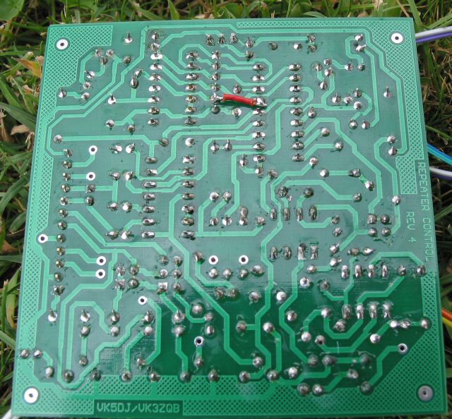
• The latest software requires a wire jumper
from pin 5 of JP1 (effectively pin 12 of the MC145436) and pin 15 of
the 16F628 on the back of the
board. Use a 1cm length of insulated wire. See LINK.JPG.
• The controller supports AC Fail indication from Version 6.10 and a hardware modification is required if you want to access that function. I have had to press the MCLR pin (normally goes to +5V for normal operation) into operation as a port. If you want to use the AC fail facility read the V6.10 manual for information on what track to cut, install a PCB pin and read the note on voltages allowed on the pin. If you do not modify the board the controller still works fine but with no AC fail facility.
Controller and the 16F628(A)
The PIC 16F628 is near enough to a plug in replacement for the 16F84 but with twice as much program memory and twice the EEDATA and RAM. The latest versions of the program contain enhanced features and use most of the 2048 bytes of memory. I recommend the 16F628 version and only provide the 16F84 version in case someone cannot source the 16F628.
Pin 15 of the PIC was unused and by reprogramming it as an I/O port, and adding a 1cm long jumper under the current board, decoding of all DTMF tones is possible. Working through a conversion table for the callsign is no longer necessary.
The 16F628 version accesses the valid tone detect from the MC145436 by linking pin 15 of the 16F628 to pin 5 of JP1. |
 |
Another consequence is that a simpler modification for a 8870 is possible as I decode the 'data decoded' output of the DTMF chip so the latching issue with the 8870 disappears.
Interface issues
The connection to the Carrier Operated Switch (COS or mute) of receivers can vary considerably from radio to radio. Here is some advice that may save some frustrating moments.
- To ease changing COS polarities:
When wiring R21 and R22 stand the resistors on end with the resistor body in the R21, R22 resistor holes closest to the centre of the board. Bend the long top lead so that it may be soldered into the correct hole near C9. The hole closest to C9 connects the resistor to +5V whereas the inner hole connects it to 0V. If at a later date you need to change polarity it is easy to snip the long resistor tail and bend it out of the way. A new wire can then be soldered into the alternate hole and soldered to the remaining tail of the resistor. Alternatively resistors R21 and R22 could be left off the board entirely and wired externally. Board photos on this site do not show these suggestions. - To cater for different COS situations use this table in association with the relevant section of the manual:
| COS output circuit | Resistor | Software |
| Open collector - neg active | to +5V | neg active |
| Open collector - pos active | to +5V | pos active |
| Off high, active low | to +5V | low active |
| Off low, active high | to 0V | high active |
- Note that when using open collector COS equipment in the positive active mode it will be necessary to tie an unused simplex port COS to 0V. This is most easily done on the back of any input plug to the controller. If this is not done the software will think the COS is active. In this mode if the main receiver is turned off the controller will interpret this as a received signal and key the transmitter. In all other modes the controller will ignore loss of receiver power and not key the transmitter(s).
- To cater for different PTT situations:
| PTT feature | Note | Software |
| 0V off, +5V to +12V active | The LEDs indicate in the reverse sense. ie LED glows
when the TX is not keyed. |
pos active |
| +3V to +9V off, 0V active | To avoid the TX LED from glowing faintly in the inactive
state you may need to add a small diode in the lead from the PTT
of the radio to the controller. This is most easily done at JP5 with
the cathode of the diode to the appropriate PTT pin of JP5 (pin 3
or 4) and the anode forming the new
input
connection
to the board. This prevents the PTT circuitry from providing a current
sink for the LED circuit, it does not affect operation of the PTT. |
neg active |
| +9V or more off, 0V active | neg active |
Note that the circuit diagram shows capacitors C14,15,18,21 with negative to the outside world. Some radios have +ve voltage on their microphone inputs. This will result in distorted audio and possible failure of the capacitors. I strongly suggest these capacitors are wired with +ve to the outside world. The circuit is wrong as is the board overlay.
Single sided board for homebrewers
I have been approached by people regarding a single sided board version of the controller. Santiago P. Sison Jr. has developed a single sided board for the 16F84 version and this link downloads photos of his work. Santiago is willing to send more detail on request. Read the included santiago.txt for details on how to contact Santiago.
DTMF Expansion
This is a 2003 project and aims to extend the power of the DTMF decoder on the VK5DJ controller board. It develops a project by Dave WW2R and saves on some parts. By extracting levels from the DTMF decoder socket it enables 8 new control ports for external items eg fans, controlling other repeaters on site, turn off the ABC TV transmitter on site to overcome TVI etc. Any polarity, fixed or variable pulse widths are supported. The circuit and board design are Dave's, the software is mine. I temporarily took this project off line as there is a reported problem with an 8870 but it works ok with a MC145436 so I've put it back by request. Let me know if you have any problems.
last updated 7 February 2010