Weather Station Data
Converter
by John Drew VK5DJ
The WM918
weather station is a popular system for home weather measurements.
The South
East Radio Group is in the process of setting up a weather station network
across the south east of
The concept
is to have an interconnected system that will provide amateurs with a regularly
updated weather reporting system for personal interest.
The data
coming out of the WM918 weather station is not structured for weather data over
packet radio. To create the format required by programs such as UI-View, an
interface such as this or a computer running an interface program is
required. This project describes an
interface to interpret the data from a WM918 station and make this available
as a string that can be delivered to a Packet TNC for transmission as either
a
beacon or as a connected packet. For information on the data structure of the
WM918
a summary is available from http://wx200.planetfall.com/wx200.txt
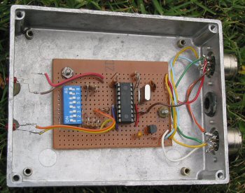 |
A view of the interface board installed in a second hand diecast box that happened to have to one 5 pin and one 8 DIN connectors already installed. |
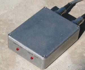 |
The outside view with leads going off to the TNC and the WM918 |
The
software in the BAS file is completely original within the context of the APRS
format for weather but I received valuable pointers by looking at a solution
published on Andrew VK5EX’s website (http://www.qsl.net/vk5ex/wx-stn/wm.htm)
– thanks Andrew. I am not sufficiently competent to reverse engineer the
solution provided by Andrew. It was easier to start again. Why re-invent the
wheel is a good question?
- Because I like a challenge
- Once I understand how to do it,
the concept can be extended with additional features, which is what I have
done here.
Andrew’s
solution has the capacity to change delays in the beacons and an option to
place the TNC in converse mode. It produces positionless packets only and
therefore requires a separate beacon from the TNC to provide position detail.
My solution
has the following aditional features:
·
Switch
between position and positionless packets
·
A
choice between connected and beacon modes
·
A
choice between Imperial and Metric data output
The beauty
of the connected mode is that it will be possible to dispense with random
beacons and provide a more controlled system for grabbing data from a range of
sites with reduced collisions.
I have also
produced a version that operates an LCD screen. It was useful during the debug
stage but once the code was right who wants another screen when the weather
station has a very satisfactory one within a metre or two?
The WM918
outputs data in a frame that is quite different from that required by programs
such as UI-View. For the SERG (South East Radio Group) network a new program
called SEweather is being written by the author to coordinate from a central
location, the reports from multiple stations and provide a structure that
avoids the problems of random beacons and enables use of the digis for other
data transfer in an emergency.
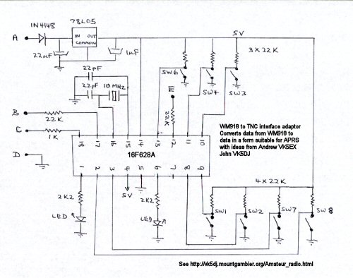
The circuit
is included as a separate file but utilises a 16F628 PIC and a handful of
resistors, capacitors and switches. The PIC runs at 10MHz.
The
following options are provided:
(1) Connected or beacon mode
(2) UI-View mode or standard TNC mode
(puts TNC in converse mode first)
(3) Positionless weather data or complete
weather data including position
(4) Send Metric or Imperial measurements
(5) Beacon period from 50 secs-35
minutes
The
latitude and longitude for a site is stored in EEDATA in the PIC. This is
accessed when a complete weather packet is required. It avoids the need to have
a separate beacon radiated from the station to establish a position on a UIView
screen and assists with the reduction of beacon clutter, especially in this
arrangement where 5 weather stations share the same network. Obviously this
mode is turned off when used in a mobile situation.
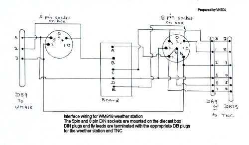
The
software was written to emulate and build on the software provided on Andrew’s website
and I have used the same connections to enable plug in capability for this
project. The 16F628 is pin compatible with a 16F84 but is a more modern device
and cheaper. To access the extra features of this solution, additional switches
are required. I do not use an “in circuit” programmer but this facility is
still available for those who require it. I have made use of one of the ports
dedicated to this, providing that switch SW6 is off, then in circuit
programming in still available.
Some
samples
This first packet
example is a complete weather packet with lat/long and includes Imperial
measurements as expected by UIview. Note that the WM918 weather station outputs
in metric units. At the time there was no wind or rain in my shack – but there
was a rain total of 78 points from my experiment with artificial rain two days
earlier.
@301902z3735.30S/14021.18E_092/000g000t063r000p0000P0078h60b10150uDJWS
Millicent weather
This second
packet is similar data 2 minutes later in positionless weather data format.
_09301904c092s000g000t063r000p0000P0078h60b10150uDJWS Millicent weather
The next
packet is in metric mode – positionless format (17 minutes later)
_09301921c092s000g000t178r000p0000P0020h60b10150uDJWS Millicent weather
Note that
the temperature in Celsius is showing 17.8 degrees while in the previous packet
the temperature was showing 63 degrees F due to slight change in temp over the
17 minutes (17.8C=64 deg F). In any case you will find a small discrepancy will
appear due to the use of integer arithmetic in the PIC.
The
difference in packets between UIdigi mode and dumb TNC mode is the addition of
a control C to put the TNC into command mode and then sending a “conv” to put
it in guaranteed converse mode, other than that they are identical. Andrew
talks about this on his web site and you will find it useful to read his
information too.
The
latitude and longitude are stored in EEDATA and can readily be changed at
programming time. You’ll have to do some arithmetic in changing the ascii value of a letter/numeral to hex – still it’s good for
the soul and few people change QTH that often. I’ve provided a table of values
later in this document.
| Veroboard view showing the drill pattern to remove copper. The left end is the switch end. | 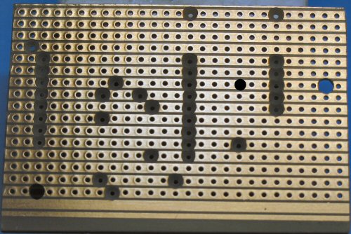 |
| Under board showing the various jumpers. | 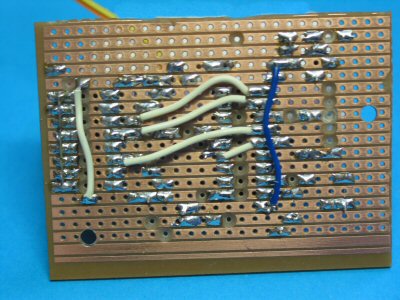 |
Here is a
list of the inputs and outputs
|
Port |
Pin No. |
High |
Low |
Comment |
|
A.0 |
17 |
|
|
Serial in
9600 8N1 |
|
A.1 |
18 |
|
|
Serial
out 9600 8N1 |
|
A.2 |
1 |
LED on |
|
LED Data
IN |
|
A.3 |
2 |
Adds 20
min to beacon delay |
No time
added |
SW8: Note all switches
position ON=LOW |
|
A.4 |
3 |
Adds 10
min to beacon delay |
No time
added |
SW7 |
|
A.5 |
4 |
Held high |
|
Programmed
as MCLRE |
|
B.0 |
6 |
LED on |
|
LED Data
OUT |
|
B.1 |
7 |
|
|
unused |
|
B.2 |
8 |
Imperial
measure |
Metric |
SW2 |
|
B.3 |
9 |
Adds 5
min to beacon delay |
No time
added |
SW1 |
|
B.4 |
10 |
Dumb TNC
mode |
UIdigi
mode |
SW3 |
|
B.5 |
11 |
Connect
mode |
Beacon
mode |
SW4 |
|
B.6 |
12 |
+10 V
connected |
-10V
discon. |
To RS232
pin 8 (DCD) |
|
B.7 |
13 |
Lat/Long
format |
Positionless |
SW6 |
Each input
(apart from serial in) is held high with a 10-22 K resistor. Input ports are in
red.
The codes
that preface data in the positionless format are:
|
Code |
Data following the code |
|
c |
Wind
direction in degrees |
|
s |
Sustained
1 min wind speed in mph |
|
g |
Gust
(peak wind speed in mph in last 5 mins) |
|
t |
Temp in
degrees Fahrenheit. Below zero shown with “–“ and max of -99 deg |
|
r |
Rainfall
rate in points/hr |
|
p |
Rain in
last 24 hrs (midnight to midnight) |
|
P |
Total
rainfall since reset |
|
h |
Humidity |
|
b |
Barometer
in millibar or hecta pascals |
|
_ |
Underline
character starts the packet |
The “u”
following the 5 digit barometric information signifies UI-view is the software
commonly used for receiving this packet (it could be anything really but I’m
not sure what happens if you duplicate one of the above codes.)
The DJWS
stands for DJW(eather)(S)tation software.
This is
followed by a text string describing the location of the system.
EEDATA memory map
|
Memory location |
Data (zero terminated strings) |
|
0 (hex) |
"@",0 |
|
2 to 1E |
"z3735.30S/14021.18E_",0 (lat/long string) |
|
1F to 26 |
"p",0,"P",0,"h",0,"b",0 (various labels) |
|
27 to 28 |
"-",0 (temp label
for minus degrees) |
|
29 to 2A |
"c",0 (wind
direction) |
|
2B to 2C |
"s",0 (wind
speed) |
|
2D to 2E |
13,0 (end of line) |
|
2F to 46 |
"uDJWS Millicent weather",0 (information) |
Note: the information string at the end of the EEDATA can be as
long as you want within the limit of the 119 bytes of EEDATA. It must have a
zero as the last byte indicates to the sending routine that it has reached the
end of the string.
You are advised not to try to edit anything other
than the lat/long starting after the “z” and finishing at the “E” (locations 3
to 1C) and the information string starting at the “M” (address 35) of Millicent
and going to wherever you please within the memory limits and leaving room for
a “0” end of string marker.
Most programmers have facility to edit the EEDATA
area. Remember that the value of the letter entered is the ascii
value in hex. But the zeroes after each string MUST be real zeroes and are
entered as 00. This equates to zero hex and is tested
as such. Look at the sample hex file to get the system.
|
letter |
hex |
letter |
hex |
letter |
hex |
|
a |
61 |
j |
6A |
s |
73 |
|
b |
62 |
k |
6B |
t |
74 |
|
c |
63 |
l |
6C |
u |
75 |
|
d |
64 |
m |
6D |
v |
76 |
|
e |
65 |
n |
6E |
w |
77 |
|
f |
66 |
o |
6F |
x |
78 |
|
g |
67 |
p |
70 |
y |
79 |
|
h |
68 |
q |
71 |
z |
7A |
|
i |
69 |
r |
72 |
|
|
|
letter |
hex |
letter |
hex |
letter |
hex |
|
A |
41 |
O |
4F |
2 |
32 |
|
B |
42 |
P |
50 |
3 |
33 |
|
C |
43 |
Q |
51 |
4 |
34 |
|
D |
44 |
R |
52 |
5 |
35 |
|
E |
45 |
S |
53 |
6 |
36 |
|
F |
46 |
T |
54 |
7 |
37 |
|
G |
47 |
U |
55 |
8 |
38 |
|
H |
48 |
V |
56 |
9 |
39 |
|
I |
49 |
W |
57 |
/ |
2F |
|
J |
4A |
X |
58 |
@ |
40 |
|
K |
4B |
Y |
59 |
- |
2D |
|
L |
4C |
Z |
5A |
= |
3D |
|
M |
4D |
0 |
30 |
<cr> |
13 |
|
N |
4E |
1 |
31 |
_ |
5F |
Timing of beacons is provided by the setting of
switches SW1, 7, and 8. The base rate of the beacon is set by the data coming
from the WM918. This comes out every 10 seconds. There are actually 5 complete reads
completed giving a fundamental repeat rate of 50 seconds. Each of the time
switches add their quotient to the total. The switch is active when open (off).
Timing of beacons settings
All three switches closed (on) = 0 volts on port
|
SW1 (5 mins) |
SW7 (10 mins) |
SW8 (20 mins) |
Result |
|
closed |
closed |
closed |
50 sec |
|
open |
closed |
closed |
5 mins |
|
closed |
open |
closed |
10 mins |
|
open |
open |
closed |
15 mins |
|
closed |
closed |
open |
20 mins |
|
open |
closed |
open |
25 mins |
|
closed |
open |
open |
30 mins |
|
open |
open |
open |
35 mins |
Beacon mode
Beacon mode may be either positionless or complete
weather modes.
Positionless beacons begin with a “_” and have identifiers for wind direction and
speed. There is no position information and the date/time is mm/dd/hh/mm
All weather information after the time is prefixed
by an identifier eg “c”, “s”, “g” etc.
Complete weather beacons begin with a “@” and have a date/time of dd/hh/mm (no month) followed by “z” to indicate Zulu
time, then lat/long, an underline character to indicate weather then wind
direction and speed separated by a “/” with no prefixes (i.e. no “c” or “s”).
The rest of the weather information follows with the
appropriate prefixes.
Connected mode (SW4 off, TNC DCD line connected to
PortB.6, SW3 on for uidigi mode)
Connected packet may be either positionless weather
(SW6 on) or complete weather with lat/long (SW6 off).
Connected mode is intended for a weather system
consisting of a number of stations whose beacons could easily cause hidden
transmitter problems. As the stations gradually drift in their timing it could
mean that data is corrupted for days or weeks. The solution is to use the
connected mode.
In this mode the outlying station is connected to by
a central station. Once a connection is identified by the remote station the
PIC sends one packet to the TNC with the most recent data. At most this packet
may need up to 10 secs to arrive. On receipt of the packet the central station
(running the SEweather program) disconnects and the remote station returns to a
dormant state awaiting the next query. The central station then either beacons
the first remote station’s information over the network or alternately holds
the information until all remotes are queried and beacon the lot in one packet.
The first alternative results in shorter packets and would be the preferred
mode.
The main aim of this process is to reduce traffic at
what could be a busy time. In addition the central unit can control the
frequency at which data is gathered and from which station.
Comment on standards
The option of sending metric measurements is
included in the PIC program as the preferred mode of operation for SEweather
will be metric. It is a pity that some programs choose to use the non standard
imperial for input – metric has been accepted by the scientific community for
100 years. Rightly the WM918 outputs metric as a scientific instrument should.
What a program outputs for a user is
another matter and must meet user needs – in cubits if need be!
Here is the hex file for loading into a 16F628A (download
Hex)
John Drew
VK5DJ