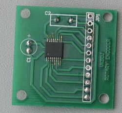
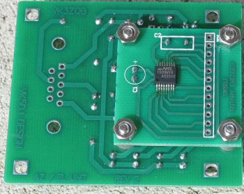
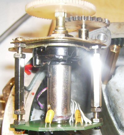
The AS5040 mounted on the old encoder board that must be adjusted relative to magnet
AS5040/45 home brewed
The AS5040/45 absolute encoder chip is a tiny 16pin SM device about 6mm * 6 mm. To use the device a small magnet (diametral magnetised - two poles on the working face) rotates above the chip. The resistance to dirt, water etc is obvious. The AS5040/45 has a number of outputs but in this project I access the digital access by clocking with a PIC16F628 and building a 10bit number. This 10bit number is then sent to the shack unit using 9600 baud which converts it to a reading in degrees to 0.1 degree readout. The 16F628 can be switched to access a calibration mode to allow adjustment of the magnet and also switched to reverse the order of the number to cater for different rotational directions. See Austria Microsystems website for info on the AS5040/45.
The AS5040 mounted on the old encoder board that must be adjusted relative
to magnet
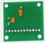
The capacitor side of the encoder board (old board)
The new board has a locating hole for the centre of the AS5040/45 and corrects
an error.
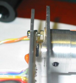
The magnet above the AS5040. Gap not very critical. But location is.
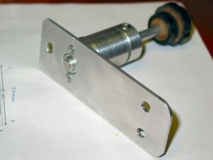
The magnet inside a small cup on end of shaft
Note large holes on plate to enable accurate location of AS5040 sub board.
This photo shows the encoder board attached to the bottom of the revised AZ/EL
board. See above re wires yet to be soldered while testing.
This layout is an option, some may prefer to use a plug and socket arrangement
(see earlier AZ/EL interface board) and separate the two boards. I prefer the
idea of fewer sockets at the antenna.
Note this version encoder board is about to be replaced with one that has the
AS5040/45 placed centrally and an error fixed (C1 must bypass pin 15).
The Rev1 bare board will be included as a 'freebie' to board orders if requested.
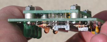
Edge view of AZ/EL and encoder boards joined showing spacers and 12 pin header
joining wires (9 connected)
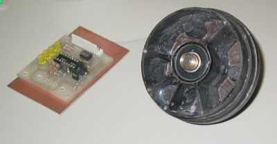 |
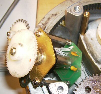
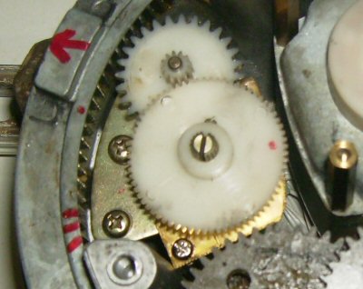
Mounting method for magnet used by Chris VK5MC. It is mounted in an old encoder unit with excellent bearings liberated from a tree harvester . The AS5040 will be attached to an adjustable plate above the magnet. 16F628 antenna mounted unit shown to left. |
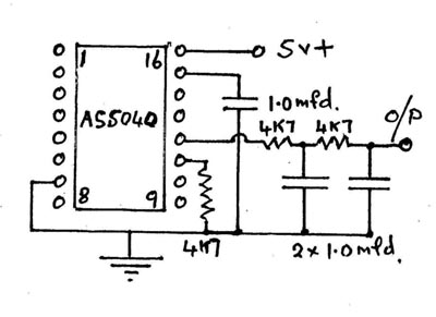
Analogue output from an AS5040/45
By integrating the PWM output available from both the AS5040 and AS5045 it is possible to output a 0 to +5V signal. A simple resistor/capacitor combination on the PWM output will do and this can then be fed to either the A/D converter in the shack unit, use it as a subsitute for the potentiometer input, or even simpler, scale it with a pair of resistors (or a potentiometer) to 0-3.60Volts and feed it to a digital panel meter direct. Tony VK5ZAI has one working in analogue mode (as of 1/6/06) as a replacement for a pot. Check his website at http://www.electric-web.org/rotary_encoder.htm. Tony has been helping me with the mechanical side of this project.
Downloads
Hex code for 16F628 AZ/EL using AS5040
Hex code for 16F628 AZ/EL using AS5045
See bottom of page for hex codes if you want to susbsitute a potentiometer in a rotator with an AS5040/5045 system as VK6MJ has done.
Example of a system in action
Here are some photographs showing how Martin VK6MJ modified his rotator with AS5045 and magnet and how he mounted things. Martin reports it is working well.
Encoder board and magnet replacing a potentiometer
Ready for mounting in the rotator
Completed installation
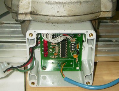
AZ/EL interface mounted on the side of the rotator
The finished system
Because the rotator gears produced a 253 degree turn of the old pot it was necessary to modify the code for the 16F628 (or 16F628A or 16F648A) in the AZ/EL Board. The modification translates the 253 degree movement into a 0-360 degrees and involves inserting some numbers into the eedata memory to allow for the arithmetic of the conversion. Contact me if you need help.
If you plan to use this solution you will need to use the code below and burn the PIC after altering the data in memory locations 01,02,03,04. of the eedata. To help you find the locations they currently hold D3 02 00 04. Don't change address 0 which has a 00 in it.
To understand these numbers you need some information. Numbers are stored in pairs and in the reverse order, so D3 02 should be read as 02D3 or 723 decimal.
If you are using a 10 bit device and A5040flex.hex then the maths is: 1024 * degrees of rotation / 360
Example 1:
So if your rotator has gearing that swings the magnet
254 degrees then the formula 1024*254/360 = 722.5 or 723 to nearest whole
number
Convert 723 to hex (use windows calculator) 723 Decimal = 02D3.
Switch the low and the high bytes and edit location 01, 02 of the EEDATA
to read D302 (as I chose the same numbers as are already there then this
step is obviously
not necessary)
Example 2:
So if your rotator has gearing that swings the magnet 310 degrees
then the formula 1024*310/360 = 881.77 or 882 to nearest whole number
Convert 882 to hex (use windows calculator) 882 Decimal = 0372. (remember that
although the calculator indicates 372 the numbers are in pairs so it is 0372
Switch the low and the high bytes and edit location 01, 02 of the EEDATA to
read 0372
What are the next numbers at location 3,4 ?
For your information the next set of numbers in eedata are 00 04 which is 0400hex = 1024 the number of counts for a 10 bit encoder. Compare this with the eedata in a 12 bit encoders software and you will find the hex equivalent of 4096. You do not need to alter these, just use the right hex file to suit your encoder. Right now the value is sitting in eedata for the day when I make these files the same and just use data to tell the program which AS5040 or AS5045 it is using. For the moment there are other differences that require the use of discrete files.
If you are using a 12 bit device eg A5045flex.hex then the maths is: 4096 * degrees of rotation / 360
Example 1:
So if your rotator has gearing that swings the magnet 254 degrees
then the formula 4096*254/360 = 2889.9 or 2890 to nearest whole number
Convert 2879 to hex (use windows calculator) 2890 Decimal = 0B4A.
Switch the low and the high bytes and edit location 01, 02 of the EEDATA to
read 4A0B (as I chose the same numbers as are already there then this step
is obviously not necessary)
Example 2:
So if your rotator has gearing that swings the magnet 310 degrees
then the formula 4096*310/360 = 3527.1 or 3527 to nearest whole number
Convert 3527 to hex (use windows calculator) 3527 Decimal = 0DC7. (remember
that although the calculator indicates DC7 the numbers are in pairs so it
is 0DC7
Switch the low and the high bytes and edit location 01, 02 of the EEDATA to
read C70D
Download A5040flex.hex
Download A5045flex.hex
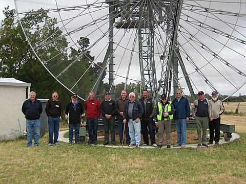
Members of the South East Radio Group (SERG) stand in front of the VK5MC
10
metre dish using AS5045s and the VK5DJ Beam Rotator System.
Chris VK5MC is four from left.
![]()
![]()