Beam Direction Indicator Project
to point a dish/beam in a required direction either through manual control
or automatic tracking
using various antenna direction encoders including: an AS5040/AS5045
magnetic absolute encoder chip, MA3-P12 device and SEI system for A2, A2T
from US-Digital, HH-05 and HH-12 from DF1SR, Screwjack output, potentiometer
output, 16 bit Gray Coded wheel and now the SCA61T inclinometer chip for
elevation.
Built in sun and moon tracking, but may
be interfaced to a computer for satellite tracking (Orbitron software)
and
EME (VK3UM EME
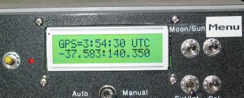
Planner software). Also supports GPS setting of date/time/lat/long for field
work.
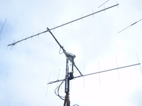
My satellite antennas controlled by the project
Screwjack elevation and the inclinometer (SCA61T) assembly above
Click the photo or here to see my satellite setup
See below how to order a set of 5 boards (click here)
Latest page change 14 June 2010 added
new versions 8.40, 9.51 and 10.0
Differences are in the clock support and 2 or 4 line LCD
Use these links to access information on the various encoders or items of ancillary equipment for the project
| Encoders |
| Auxiliary equipment |
![]()
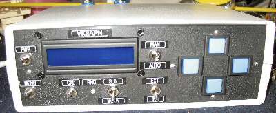
Stan LZ2STO has a great looking example of the controller
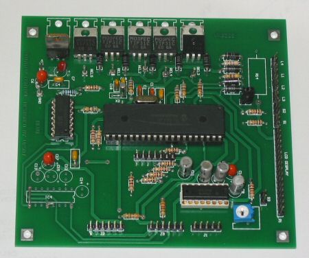
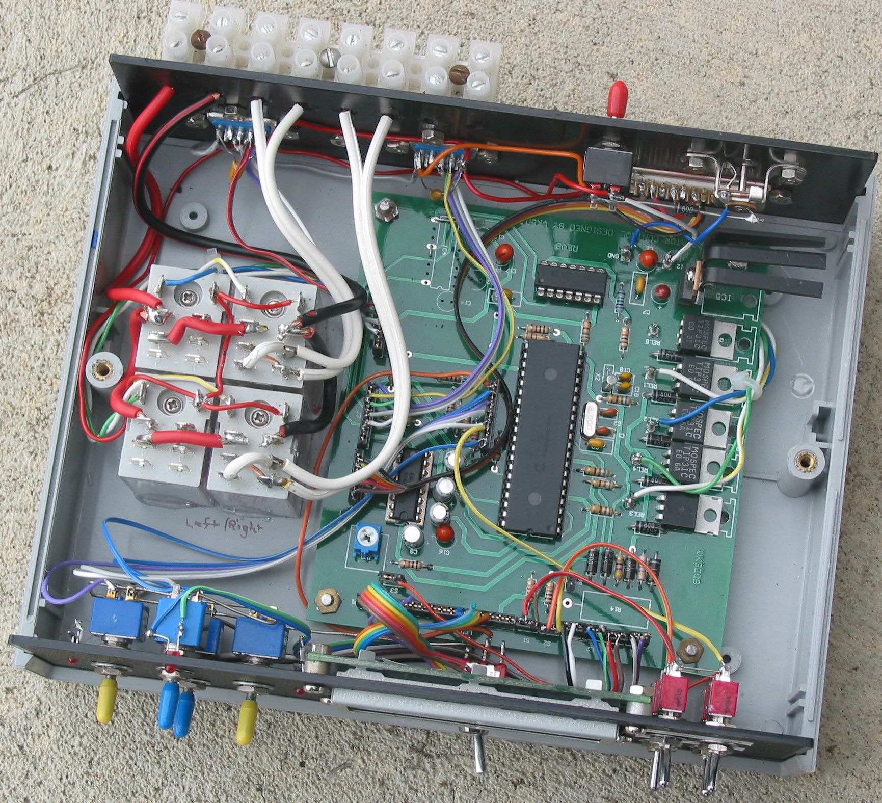
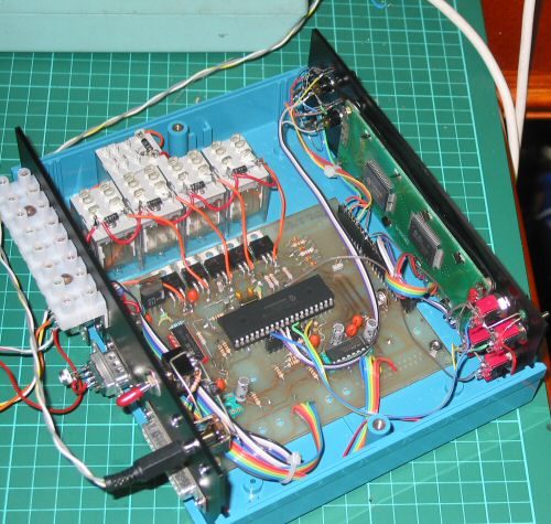
The populated shack controller board
The board is fully populated (one MAX232
is unused except for SEI connections) ready to have switches, LEDs, LCD
etc plugged in. It's a simple board thanks to the power of the PIC18F4620/82/85.
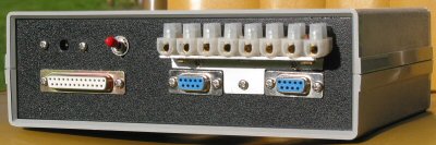
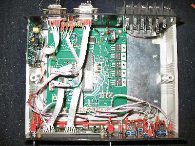
Rear view of VK5DJ's controller showing connections
DB25 to computer, DB9s to antenna units
Power socket and switch top left, with direction motor terminals top right.
Top view of new board in old case. Note brake relay not fitted.
I prefer the layout with the relays on the right, not on the left as shown
here.
Click on image for large version of photo (564K)
The encoders supported by this project have grown considerably since the first writing of this page. When reading the description below be aware that it was written when there were few inexpensive solutions to encoders on the market. This is why the description focussed on the AS5040/45 chips as being an opportunity to do something well at resonable cost. Since then a number of encoders have come on the market that use these chips (or other technologies) but save all the alignment problems. Further requests to support other encoders has resulted in the project growing. So when reading the description below be aware that the home brew AS5040/45 solution is just one of a number of ways you can use the project. I have devoted a page to each of the encoder solutions - see above links.
The Project
With greater interest in EME and satellite operation it became clear that there was room for another beam direction indicator device. Technology too has moved on and although there are many amateurs with bottomless pockets and a wish to buy commercial, there are also many amateurs who like to roll their own as much as possible.
Companies such as AustriaMicrosystems have produced Hall Effect Devices for some years but in recent years the appearance of their devices with 10 bits (1024 positions) and now 12 bits (4096 positions) has opened other absolute encoder options. Some amateurs have used US Digital optical absolute encoders with success or home made Gray Coded wheels. All have strengths and weaknesses, all have errors of some sort and all present different challenges be they cost or construction problems.
In early 2005 I read of the AustriaMicrosystems AS5040. I suggest you look at their website: http://www.austriamicrosystems.com/
At GippsTech Symposium in July 2005 I presented some early work using an AS5040 mounting sytem developed with the assistance of Tony VK5ZAI and his lathe. A second presentation was made the following year to describe progress to date and demonstrate the AS5045 in action.
This page provides an overview of the latest version of the project, as of November 2007, and discusses the pros and cons of the AS5040/45. See this link to the AustriaMicrosystems FAQ site for further comments on accuracy.
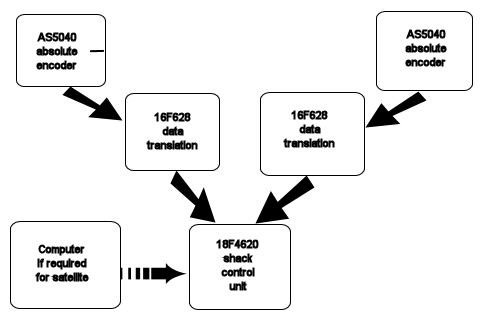
Two AS5040/45s mounted at the antenna provide direction information for Azimuth
and Elevation.
Each of these feed a 16F628 PIC which translates the polled serial data
from the AS5040 to an ASCII data stream sent serially at 9600 baud to the
shack
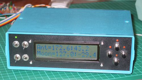
unit where information on antenna direction and calculated sun or moon
direction are correlated and the antenna direction motors switched manually
or automatically.
Before a description of the devices is presented a few comments on accuracy. An examination of the data sheet for an AS5040 (and the AS5045 is very similar) reveals that for a centred magnet, tracking accuracy will be within +/- 0.5 degrees (or better), while with an uncentred magnet (0.25mm) there may be errors up to +/- 1.4 degrees when commercial considerations in positioning, temperature, A/D noise etc are taken into account. The location of the die within the package may vary up to 0.235mm..
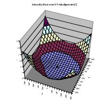
Magnet location chart
Lower scales +/
- 1mm
Vertical scale error 0-6 degrees
Other errors
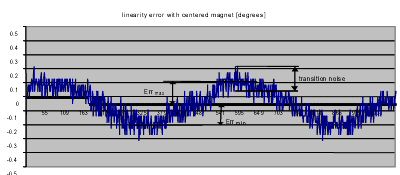
This chart shows over 360 degrees the errors due to internal gain, A/D conversions
and mismatch. Note noise.
So what does this mean in practice?
There has been a question around tracking, the data sheet provides useful information. Keep in mind that the accuracy of the system is largely determined by accurate placement of the magnet, so no sloppy mechanics.
For the test jig I arranged for two devices, AS5040s with magnets and two 16F628 translator boards, to be coupled front to front. That is one device operated 0 to 1023, while the other turned in the reverse direction, that is a count of 1023 to 0.
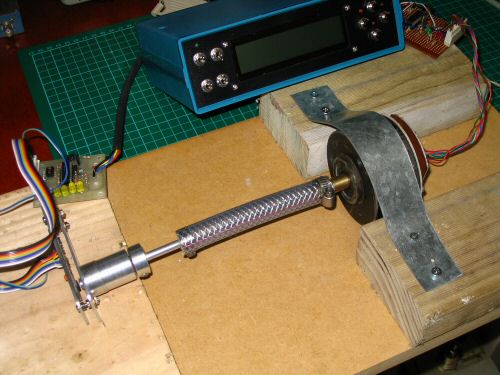
Photo shows basic setup for test, note Chris VK5MCs encoder setup (right)
mounted in an old incremental encoder's case to make use of the nice bearings.
The boards fed to my shack unit - one to the Azimuth and one to the Elevation input. Software on the PIC16F628 translator board enables a reversal of the numbers coming from one of the AS5040 chips to cater for different mounting configurations. I used this facility to physically reverse direction but watch measurements move in the same direction . Therefore I was able to arrange the coupling so both AZ and EL read 0 degrees and as I rotated the coupling watch them 'track' in the same direction - I took readings every 5 degrees. I then put the numbers in Excel and produced the following graph. I shifted the zero line to show a symmetrical pattern as a + and -.
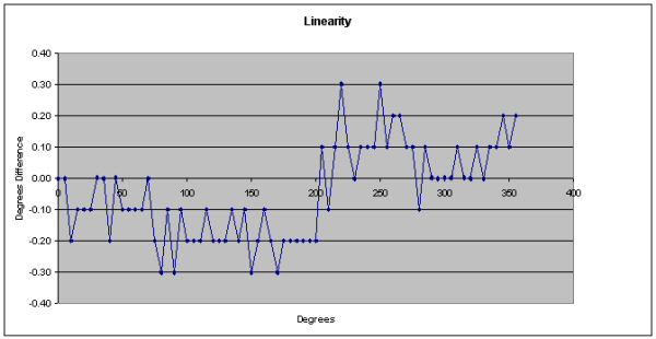
In case I had a fortuitous set of readings I then introduced a software offset on one of the data streams and re-adjusted the coupling to provide identical readings of degrees. So although one decoder was counting 0-1023, the other 'effectively' counted 1108-85. The encoders were now working on a completely different section for comparison. Again, I could see a similar pattern as above. In neither test did I see large variations of tracking as I would expect from errors moving in and out of phase. A test, shifting one encoder 10 degrees, was also completed with similar results. I plan more tests including additional rotational positions and at least one other technique, but an initial conclusion is that 'better than +/- 0.5 degrees' seems to be readily achieved, especially as our magnet alignment technique can still be improved. No temperature changes were attempted.
The magnets are not yet perfectly aligned, we're using big holes to allow adjustment. At this point it seems better than the data sheets state, but then again responsible manufacturers should warn us of worse case not best case situations.
I propose to add a calibrate function to the software, there is a switch to support this. The basic idea is to add a push button to the front panel. To calibrate, the beam is accurately aimed at the moon (using noise or signals) then the button is pushed. This will place an offset (if needed) in memory which will enable more accurate tracking over a small part of the sky. Over time a number of offsets might be used to build an error table in memory to minimise across the range of the encoder. If this idea works then it may be worth going for the AS5045 as I think software could then MAYBE take advantage of the extra 2 bits. More work to be done. The method will also have the advantage of correcting for lack of symmetry in the beam/dish rotation mechanism. I'll treat this as a future improvement.
Resistance to RF has not been fully tested apart from a 2M handheld rig running 2 watts had the antenna placed within a few hundred mm of the AS5040 and no effect was seen. I will test the device at 23cm and 70cm too.
A reality check is also necessary as beams and dishes have inherent errors too, irregularities in foundations, flexing, uneven rotating mechanisms all add to the uncertainty of 'Where is my antenna pointing?' For all but the best amateur EME stations this system will provide very usable data and control. Check your antenna's beamwidth to bring things into perspective.
For more information refer to the austriaMicrosystems site. Here is a link to the FAQ page, it makes interesting reading.
The AS5040 based beam/dish controller unit - how does it work?
The AS5040 chip consists of a ring of hall elements placed at the centre of the IC in a circle of 2.2mm diameter. The hall elements pick up the field of a magnet placed above this hall array. This information is digitized and fed into a digital signal processor which calculates the angle of the magnet with a resolution of 0.35 degrees or 1024 positions per revolution at a sampling rate of 10 kHz (assuming magnet is accurately placed). The AS5045 provides 4096 positions per revolution and a resolution (but not accuracy) of better than 0.1 degrees.
The digital angle information is available in several formats; as a serial 10 bit (or 12 bit) data stream, as a pulse-width modulated (PWM) signal or as a quadrature incremental signal.
Essentially a magnet is placed on a shaft attached to the shaft moving with an antenna in the vertical plane and another with a shaft for the antenna movements in the horizontal plane. This provides for azimuth and elevation of the antenna (or dish). The magnet hovers above the AS5040.
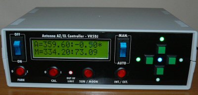
A 16F628 located near the AS5040, communicates with the AS5040 and converts it to a serial stream for reading in the unit located in the room below. Two devices are required for a complete satellite or moon tracking system and are catered for in the main unit - hence the two readouts on the LCD. Accuracy to the nearest 0.35 of a degree.
The 18F4620 polls the devices at the antenna and converts the 1-1024 number stream to degrees of movement. Another serial connection can be made to a computer providing information on the location of satellites.
Moon and sun tracking software is contained in the PIC program and enables all the direction control from within the unit. An external computer is not essential.
With the successful development of Moon Finder and Sun Finder programs within PIC memory, the PIC is now a choice of 18F4620 (or 18F4680) for Version 7.02 to provide a real time clock and manage the maths - it has 65K of memory, enough for 32K instructions OR a 18F4682 or 18F4685 with 80K and 90K of memory respectively for Version 8.00. The advantage of the bigger chips is that I have been able to restore a more accurate doppler calculation and add support for the SCA61T inclinometer chip in Version 8.00. All chips are pin for pin compatible, no hardware changes are required.
I have maintained a capability so that a satellite tracking program that outputs the right data (Az and El for the satellite) will be able to control the beam. Because the sun's apparent motion is much easier to calculate, the sun routine is producing results within 0.01 degree of the astronomical almanac. The latter is useful for direction calibration purposes using shadows or sun noise. The moon calculations are usually within 0.1 degree but may be up to 0.2 degree out. A similar result to many other tracking programs. I use the program AA.exe as a reference.
Here are the features:
At the antenna
Various solutions are possible at the antenna.