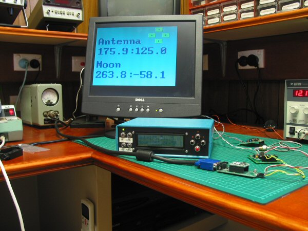
Overall view of monitor, shack unit and adapters
Click on image for larger photo
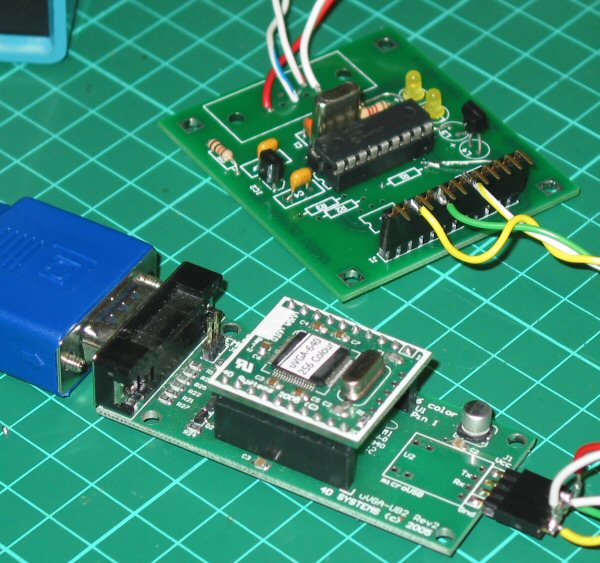
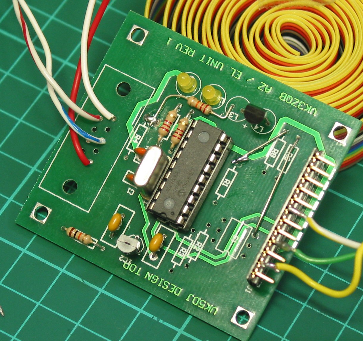
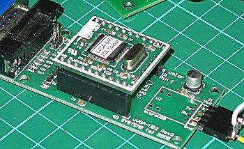
The Micro VGA sub board and mother board connected to the PIC16F648A interface to the shack unit
Click on image for larger photo
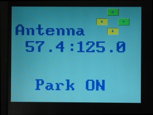
Park switch on and buttons indicate the shack unit is in the process of parking the antenna
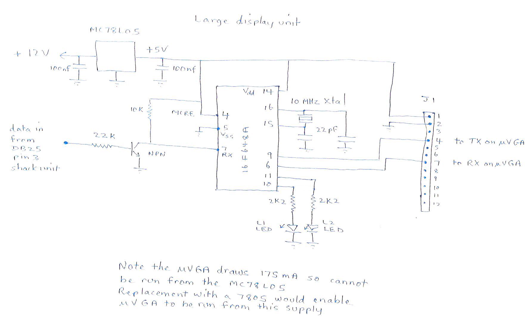
The u-VGA (640*480) video interface takes serial data and displays this on a computer monitor. See the data sheet on the Dontronics website. For maximum speed I have chosen to use an external PIC interface rather than giving the shack unit more to do - it is busy enough doing its other tasks. The interface I have designed uses an AZ/EL board to do the conversion. An inverter transistor is added to invert the data coming out of the computer interface on the shack unit and remove the -ve going pulses of the RS232. The PIC16F648A (the program is too large to fit in a 16F628A) requires non-inverted TTL data. The converter board communicates with the shack unit at the standard speed of 9600baud while the uVGA device will take a wide range of speeds but in this case I have set the interface to the uVGA at 19200baud. A document describing the interface system is currently being written.
Buttons on the screen indicate the current state of the relays controlling the antenna. If the Park switch is activated the display changes accordingly. In the photo the left and down buttons are depressed. Because I have changed the requirements it is necessary to use version 5.62 software in the shack unit. This will become available when I have finished the documentation.