Satellite System at VK5DJ
My satellite system effectively tracks satellites using the beam rotator project in external control mode. I use Orbitron to calculate the satellite position. I've written Version 8.11 of the shack unit software as I found that my hysteresis software wasn't working correctly in earlier versions.
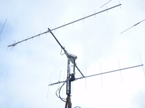
The completed antenna system for 2M/70cm satellites. Both yagis are based on the DL6WU design produced by my Yagi Calculator program. The 70cm antenna is a 16 element one with an estimated gain of 14dBd while the 8 element 2M yagi has an estimated gain of 10.4dBd. The screwjack provides elevation movement of about 100 degrees. The aluminium box at the top covers the SAC61T inclinometer encoder system described elsewhere on my site. Readout is more than adequate for satellite work and the antennas in use. The photo makes it look as if the antennas are not aligned, it's an optical illusion, they are.
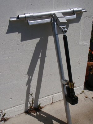
Prior to fitting the horizontal bar this photo shows the essential construction
details of the antenna head system.
(This was manufactured by Tony, VK5ZAI, thanks Tony)
Thank you Stan LZ2STO for
the 18 inch screwjack. It provided the incentive for me to finish my satellite
system. Thanks too to Seb DG5CST for the inclinometer chip.
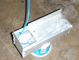
The elevation encoder assembly ready for installation on the unit above
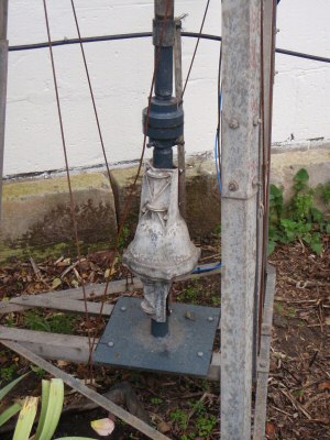
The azimuth movement is provided by an old CDE44 rotator. The
potentiometer providing azimuth readout has been modified (see this
page for details). Above the rotator can be seen a universal joint from
a piece of agricultural
machinery - kindly donated by Chris VK5MC from his excellent farm shed. This
addition enables some flexing of the vertical pipe and corrects for slight
misalignment. The black horizontal pipe near the top of the photo is part of
the sprinkler system for this garden area at the back of my radio shack. Special
permission was granted by the XYL to grow a small tower in one of her gardens!
Special thanks to Chris VK5MC for his work on the mechanicals of the tower
and for braving the dizzying height of the top assembly.
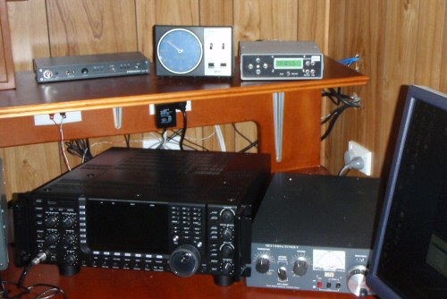
The above photo shows the Beam Rotator box to the right of the KR2000RC controller
for the main beam antenna system. The computer runs Orbitron and the VK5DJ
interface system to enable tracking of satellites. For moon and sun tracking
it is better to use the internal computations in the beam rotator project
itself - they are more accurate.
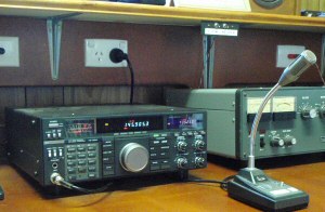
The TS790A is used for my satellite and general FM/SSB contacts
Above the FL2100Z can be seen the switches to change antennas via relays in
the shed
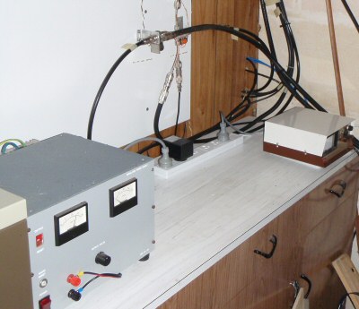
I have placed the power supplies and CDE44 controller outside the shack in
the main shed ('shed' is Australian for 'garage' where interesting things
happen - like metal work, soldering, fixing things and sometimes a fridge
to store a drink for when mates come around. All Australian males either
have sheds or wish they did have). It
is
also where
the relays
for changing antennas are located.
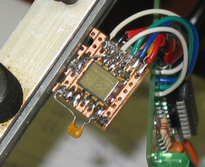
The SCA61T accelerometer that provides the elevation data is shown on bench
test. See the separate page on how
this is setup.
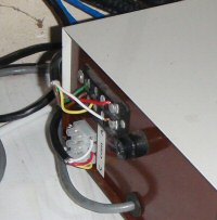
The additional 3 terminal block on the back of the CDE44 controller is wired
in parallel with the left and right key switches. The central brake key switch
is wired ON permanently to place power on the transformer at all times.
The CDE44 does not have a brake fitted (apart from a clutch arrangement)
so it does not matter if the switch is always on. The transformer
does get warm but I only switch power on to the unit when I need to rotate
the antennas.
Problems encountered in installation
Thanks
Special thanks to a lot amateurs that helped with the project with equipment or time and ideas VK5ZAI, VK5MC, VK5HDW, VK5DK, VK5AKJ, LZ2STO, DG5CST and encouragement from many others
Update 28 May 2009