SCA61T inclinometer chip
The SCA61T is an inclinometer chip by VTI Technologies. [Datasheet SCA61T] . You must purchase the SCA61T-FA1H1G to cover +/-90 degrees.
Here is one source in Germany.
Here is one in Digikey US
To use in the VK5DJ Beam Controller Project you need to mount the chip on a small piece of veroboard and connect to one of the AZ/EL boards.
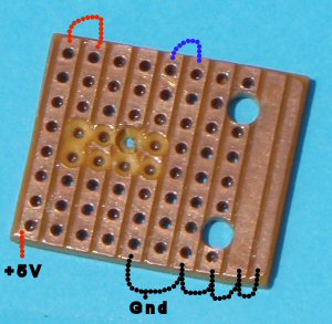
Piece of vero board ready for SCA61T.
With trace numbers from left to right:
1= Vdd with jumper at top to pin 8 and 100n bypass
2= pin 1 of chip (Clk)
3=pin 2 of chip (MISO)
4=pin 3 of chip (MISO)
5=pin 4 of chip (Gnd)
6=CSB with jumper at top to pin 5
of chip
7,8,9,10 to trace 5 all to ground.
100nF caps from +5V to gnd, one at top, one at bottom.
Here are the connections for the SCA61T-FA1H1G:
| SCA61T pins | PIC pins | J1 pins |
8 Vdd |
14 Vdd | 1 |
| 4 Gnd | 5 Vss | 2 |
| 2 MISO | 17 | 6 |
| 3 MOSI | 6 | 7 |
| 1 CLK | 18 | 5 |
| 5 CSB | 9 | 4 |
The PIC pins are included in the table as a double check only.
A power supply bypass capacitor of 100nF must be included from Vdd (pin 8) to the ground plane and placed as close as possible to the chip. Pins 6,7 of SCA61T left unconnected.
The 16F628A in the AZ/EL unit must be programmed with this hex code.
Switches on the AZ/EL unit
Normal operation all switches off.
To test AZ/EL unit with Hyper Terminal on a computer use the serial port and an inverter transistor. Put SW1 and SW2 switch ON. A small 200ms delay occurs between packets to allow better observation and the LED on pin 11 of the 16F628 will flash each time data is sent to the computer.
SW1 on the AZ/EL unit overcomes the need to be polled by the shack unit while SW2 puts the data out in ASCII format.
SW3 is unused for this encoder and should be in the off position.
LEDs
LED1 will flash once on start up of the AZ/EL board and confirms
that the PIC is functioning while LED2 flashes every time data is sent out
the serial port to the shack unit.
They could be left off the board but they are useful to monitor faults. LEDs
3 and 4 are not used.
HEX code for shack unit
The shack unit must have the Shack Code burned into an 18F4682 or 18F4685 chip. Note the code has grown and will no longer fit into an 18F4620 although I will possibly produce a version with some options removed so that the 18F4620 can be re-used. (Most likely remove some of the more exotic encoders as use of these will exclude an inclinometer anyway).
Code for an 18F4682 here. Note same code works in an 18F4685
Click here for Version 8.00 manual in PDF
The shack unit must be set for the inclinometer. This appears
in the menu with the EL encoder setting. Options for elevation encoder are
now: 10 bit, 12 bit, 14 bit, 16 bit, SCA61T.
Unfortunately the 16F628A does not have the power to support float solutions
to ARCSINE in the 16F628 so it is necessary to send the raw 205-1843
count from
the inclinometer
to the shack unit where the ARCSINE may be calculated in the 16bit chip.
Calibration
The unit I tested had a small offset different from the standard 1024. In fact I used 1035. I have added a menu item (new 27) to allow for adjustment of the offset.
Here is a description of how you might calibrate the inclinometer chip.
(1) with no elevation offset on the shack unit (use menu item)
(2) check that the inclinometer seems to provide readings from -90 through 0 to +90 degrees (or approximately so)
(3) hold working inclinometer system vertically with the arrow pointing up. If the reading does not reach 90 degrees but instead changes to -89 degrees then
(4) add 1 to item 27 ie the SCA61 calibrate menu item.
(5) check for 90 degree reading again and if necessary repeat (4) until it does reach 90 degrees without flipping into negative -89 degrees.
(6) If the reading cannot be made to reach 90 degrees and flip into the negative degrees reading then you probably need to subtract 1 from the menut item SCA61 calibrate.
This exercise should be done slowly as the chip also reacts to acceleration. I do it by clamping the system in my PCB vice and slowly rotating. The calibration system isn't unduly critical as we do not use the area > +45 degrees and <-45 degrees. Although an adjustment of 9 in the offset will change the higher angles substantially it has a minimal effect around 0 degrees.
Important menu items in the shack unit for this encoder
Menu item 8 ensure elevation is set for serial (XXX/serial).
Menu item 11 re elevation spread. Leave at default 360 degrees.
Menu item 19 re elevation hysterisis. Default 10 but set to suit your situation.
Menu item 26 re definition of encoder on elevation (10,12,14,16 bit, SCA61T). Set to SCA61T.
Menu item 27 re calibration of SCA61T. Default 1024 but adjust if necessary, see above.
Menu item 13, 30 re elevation offset. Best results set to 45 and add offset.
Possibly menu items 16, 17 elevation low stop and high stop, Default 255, -5
Accuracy
I have not conducted tests to determine accuracy. The following is a theoretical comment. There are substantial differences between counts at the lower end of the scale (0 degrees) and the top end ( 90 degrees). A single axis device such as the SCA61T will not have the high elevation accuracy of a dual axis device. By using the range -45 to +45 we avoid the poor part of the device's sine curve. Look at the data sheet for more information. The manufacturer claims good accuracy around the zero degree position and it can be seen that a change of one count represents about 0.07 degree. Near 90 degrees a change of 1 count represents from 1-2 degrees, not good enough for EME, while at 45 degrees a 1 change in count equates to an angular movement of 0.1 degree. So by shifting the range from -45 to +45 by tilting the SCA61T, it enables 0.1 degree movements for the range 0-90.
The above comments do not take into account errors in linearity. If all else fails you can always use the calibrate switch to give reasonable accuracy for a pass once the beam is aligned on the moon. For satellite use an inclinometer chip will be plenty accurate enough using any method, including no displacement, as few satellite predictions or antenna beamwidths would make this an issue.
Mounting
To achieve the greatest accuracy I do not use 0-90 degrees but instead use -45 to +45 degrees where the accuracy is greatest. I correct the reading by adding 45 degrees to the elevation offset and mount the unit at an angle of 45 degrees down. A photo of my new antenna system will make this clear.
The photographs show how I have mounted the SCA61T.
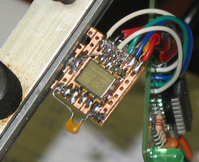
Showing wired SCA61T held in testing position
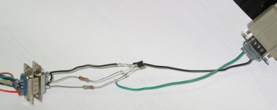
Connection of AZ/EL unit to computer RS232 with an inverter transistor
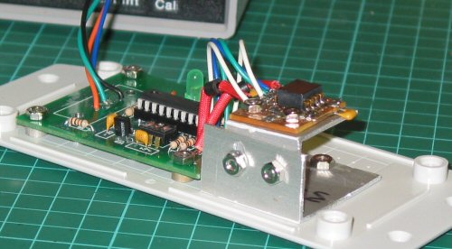
Side view of AZ/EL board and inclinometer with slotted adjustment of tilt
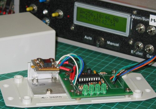
View shows mounting into base of weatherproof box with box in background
and shack unit showing azimuth of 46.8 degrees after a positive offset
of 45 degrees added to elevation reading in menu .
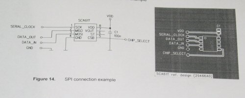
Suggested PCB as per data sheet for SCA61T but I successfully used a small
piece of veroboard.
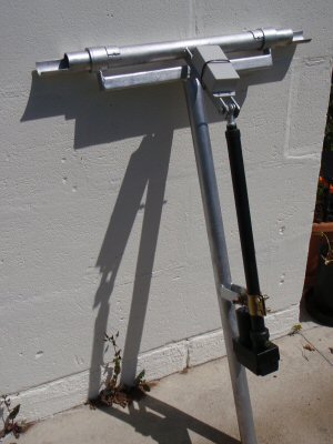
SCA61T box in future position on thruster bar for my satellite system.
Screwjack courtesy Stan LZ2STO, mechanical setup courtesy Tony VK5ZAI (thanks
friends)
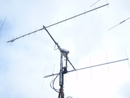
The finished system. The SCA61T and the interface board are located in the
aluminium weather protective cover. The 45 (approx) degree tilt down when
the
antennas are horizontal is described above. Special thanks to Seb DG5CST for
the SCA61T
![]()
![]()