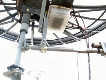
Charlie VK3NX's elevation screwjack in action
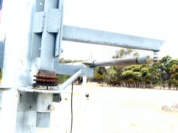
Charlie VK3NX's azimuth screwjack
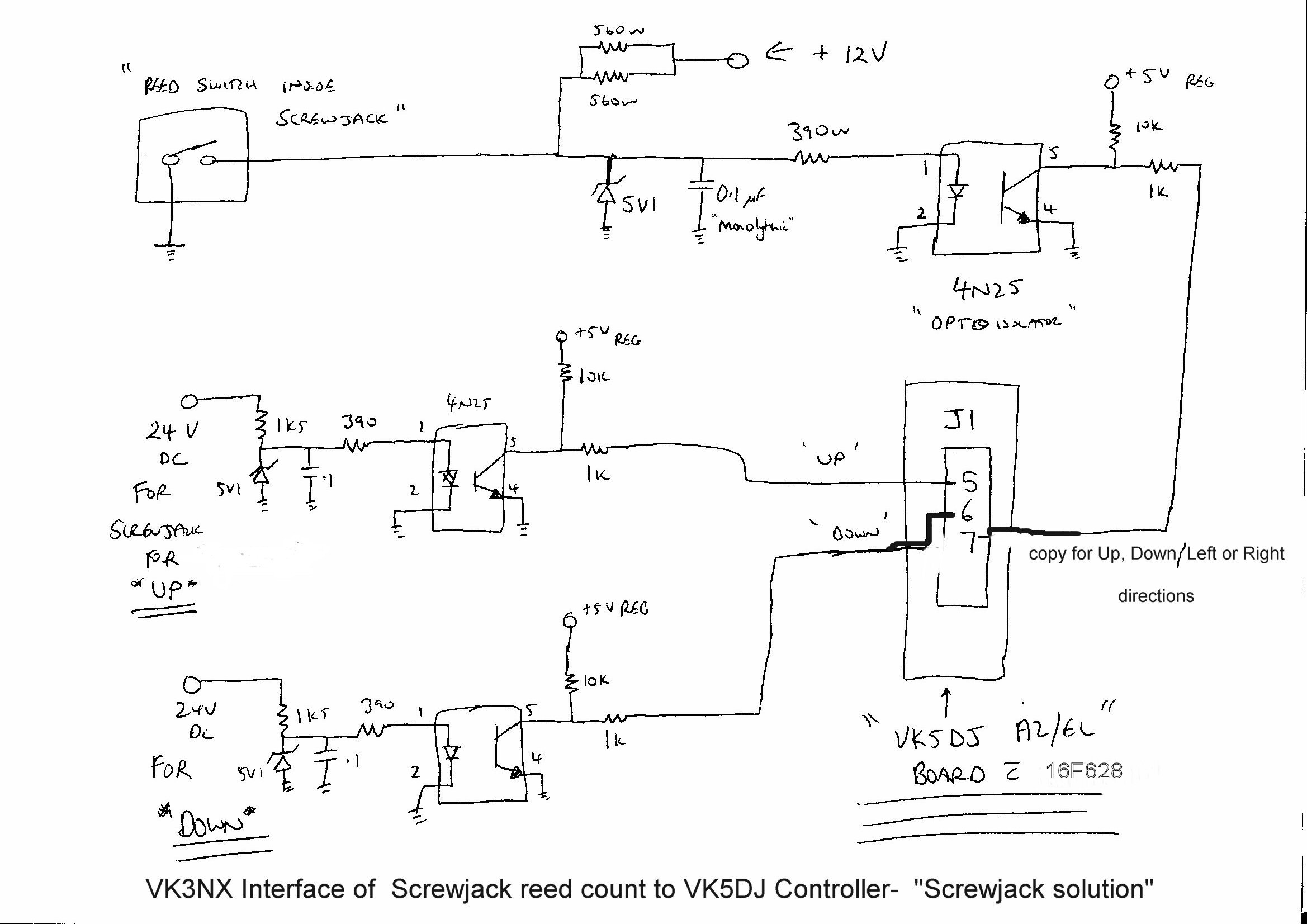
Screwjack Solution
Charlie VK3NX's elevation screwjack in action |
Charlie VK3NX's azimuth screwjack |
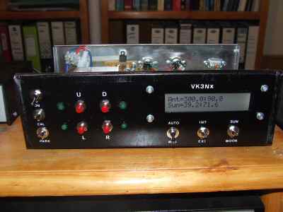
Charlie's azimuth and elevation readout
Firstly it should be noted that screwjacks use a pulsing system to keep track. They are not absolute systems (generally). Whenever the power is lost from the AZ/EL unit the direction will be lost. When this happens, the antenna will have to be taken back to 0 heading and the re-calibrate switch triggered.
Screwjacks provide a mechanism for moving a small dish. They
often contain microswitches or magnetic reed switches that operate when the
dish
moves. It
is also necessary
to provide information about the direction of travel. So in essence there are
three switches.
1. Pulse count of movement
2. Up switch
3. Down switch
My solution makes use of the AZ/EL board, part of the set of 5 boards provided
for my beam indicator project. Essentially, the following connections are made
on the encoder board connector on the AZ/EL unit – J1
1. "Count in" connects to pin 7 of the connector
2. Direction switch “Up” connects to pin 5
3. Direction switch “Down” connects to pin 6
Either the old or new AZ/EL boards can be used for this purpose. The circuit of the AZ/EL board remains substantially the same except for the interconnections described in this document. The correct software must be loaded. This is called Screw.hex
The 16F628 (or A) is again used, although a 16F648A would also be suitable.
The program adjusts to the range of the screwjack but in order for this to happen some values must be placed in eedata of the PIC.
Because each screwjack arrangement is different the user will have to develop their own corrections table as described here, so programming facilities will be required.
Charlie, VK3NX has developed an interface from the screwjack to the AZ/EL Board running the screwjack program. Normally, two interfaces will be required for a complete azimuth and elevation system. The board requires three inputs. One from the switch on the screwjack and the other two inputs sense the direction of the motors. In Charlie's diagram it is shown as 24V from the motor drive but voltage is not critical and any reasonable value from 5 volts DC up should be fine as Charlie has a 5V zener across the input.
Click for a larger image
Problem with noise
CharlieVK3NX notified me recently that occasionally his unit was jumping readings on the azimuth screwjack reading. Here are Charlie's comments, note that he uses screwjacks for azimuth and elevation.
"I did some further investigating and everything pointed to the count in being wrong /too fast/bouncy etc... I swapped PICS from the elevation unit and it also behaved very strangely yet was fine in the elevation circuit.... so I put the CRO on the input count from the azimuth screwjack and found a whole lot of noise, the full 5v on the input count pin. When the noise was there (not always) the pic certainly would count ALL transitions from low to high.... it's quick! The noise was only there in Fast rather then Slow or Pulse mode... I did check out power supply etc....but this was fine so I opened up the screwjack and found the reed switch was not centred but had come adrift only a little.... I re-aligned and gave the magnet and reed switch casing a good clean and presto....noise gone and azimuth unit counts smoothly......"
Downloads
Download the manual here.
Download the hex file for the 16F628 here
![]()
![]()