

J.F.Drew © 2000-2017


Mobile menus
VK5DJ
AS5040/45 encoders
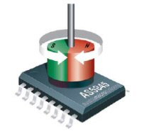
The chips consists of a ring of Hall Effect elements placed at the centre of the IC in a 2.2mm diameter circle. The elements pick up the field of a magnet placed above this array. This information is digitised at a sampling rate of 10kHz and fed into a digital signal processor which calculates the angle of the magnet with a 0.35 degrees resolution or 1024 positions per revolution for the AS5040 (assuming magnet is accurately placed). The AS5045 works in a similare way but provides 4096 positions per revolution and a resolution (but not accuracy) of better than 0.1 degrees.
The digital angle information is available in several formats; as a serial 10 bit AS5040 (or 12 bit AS5045) data stream, as a pulse-width modulated (PWM) signal or as a quadrature incremental signal. I use the I2C serial data stream.
The encoder is constructed with a magnet placed on a shaft, the latter being attached to an antenna in each plane. This provides for azimuth and elevation of the antenna.
A 16F628 located near the AS5040/45, communicates with the chip and converts it to an ASCII stream for reading in the unit located in the room below. Two devices are required for a complete satellite or moon tracking system. Accuracy is better than 0.3 of a degree with resolution of about 0.1 degree.
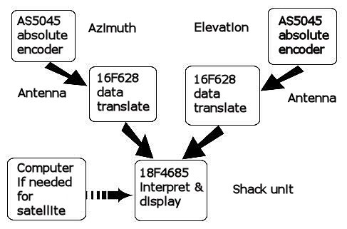
Communication flow
(click for larger view)
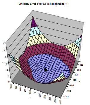
Accuracy relates to magnet position (click image)
Lower scales +/ - 1mm
Vertical scale error 0-6 degrees.
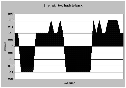
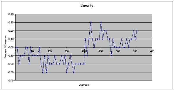
Error map with two AS5040 encoders back to back in test jig. Error is doubled as the two encoders move in and out of phase. Click for larger image.
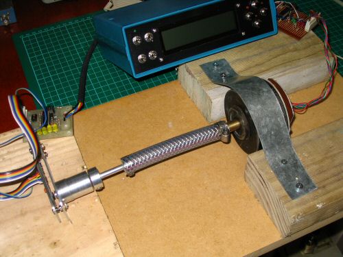
The test jig setup, two encoders joined back to back and tracking the sum of the errors.
The information on this page is provided for those who already have my boards or have made their own. As most people are now using ready made encoders such as the HH-12 or similar, I have NO stock of these AS5040/45 boards and will no longer supply them. In addition I am now providing the Mark1 AZ/EL board which is perfectly fine but lacks a trace that set the mode on the AS5045. Pin 6 on the AS5045 should be earthed or left open.
Tracking and readout accuracy
There has been a question around tracking accuracy, the data sheet provides useful information. Keep in mind that the accuracy of the system is largely determined by accurate placement of the magnet, so no sloppy mechanics.
For the test jig I arranged for two devices, AS5040s with magnets and two 16F628 translator boards, to be coupled front to front. That is one device operated 0 to 1023, while the other turned in the reverse direction, that is a count of 1023 to 0.
The boards fed to my shack unit - one to the Azimuth and one to the Elevation input. Software on the PIC16F628 translator board enables a reversal of the numbers coming from one of the AS5040 chips to cater for different mounting configurations. I used this facility to physically reverse direction but watch measurements move in the same direction . Therefore I was able to arrange the coupling so both AZ and EL read 0 degrees and as I rotated the coupling watch them 'track' in the same direction.
I took readings every 5 degrees. I then put the numbers in Excel and produced the following graph. I shifted the zero line to show a symmetrical pattern as a + and -.
Note these experiments were done with the AS5040 the 10 bit chip before I had access to the 12 bit AS5045.
The 10 bit plot in Excel
Martin’s VK6MJ home brew encoder for rotator mount
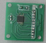
AS5045 in position on an encoder board. No longer stocked.
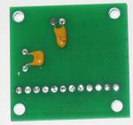
The AS5040/45 capacitor side of board
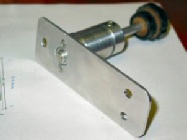
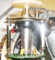
Magnet mounted in bearing
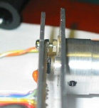
Closeup of magnet above AS5045
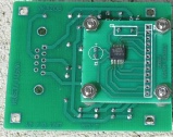
Encoder board attached to the AZ/EL board. Designed for a more compact mounting solution. Note encoder board no longer available.
If desired the AS5040/45 may be setup in analogue fashion. The chips output a PWM signal which can be integrated using a simple filter. If fed into a reasonably high impedance the output will be a voltage that varies between 0V and about 5V which canbe used to describe some of the older tracking designs that use a variable voltage input. Tony, VK5ZAI, uses this approach with his SatTrak. See his website:http://www.electric-web.org/rotary_encoder.htm
An even simpler tracking solution can be made by scaling the 0-5V output to 0-3.60V with a pair of resistors (or a potentiometer) and feed it to a digital panel meter direct for direct readout of degrees.
During the early experiments with AS5040s I received a lot of help from Tony and his lathe. You can see his work in some of the above photos.
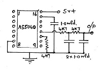
Circuit for use with an AS5040. If used with an AS5045 check the datasheet to confirmpin connections.
| Repeater features |
| Solar version |
| 1750Hz decoder |
| Record and playback |
| Voice interface |
| Micor solution |
| Yagi Calculator |
| RD Contest logger |
| Moon Tracking |
| Orbitron interface |
| PRFCalc |
| TAIT programming |
| Proton Development Suite |
| Old crystals for radios |
| Compound interest |
| Yagi photos |
| Bird proofing |
| Bender |
| VK5DJ downloads |
| VK3UM downloads |
| Site map |