

J.F.Drew © 2000-2017


Mobile menus
VK5DJ
Wiring and using the AZ/EL board
This unit is the core of the antenna system. In most applications there will be two of these boards located at the antenna. One for azimuth and one for elevation. The boards communicate with the shack unit with 9600 baud ASCII.
Each board, depending on the program in the PIC, will communicate with a different sensor. Currently the board will communicate with home brew AS5040 or AS5045 system (accesses data from the chip directly), the MA3-P12 from US-Digital (interprets the PWM output), the Screwjack solution (Counts pulses), the HH-05/12 (accesses data from the chip direct) and the SCA61T inclinometer.
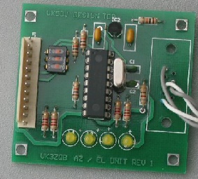
Photo right: The AZ/EL interface unit outputs ascii to shackunit.
Plug to AS5040 board to left, power and data out to the right. There are extra LEDs for magnet alignment.
I recommend that the wires between the encoder and the board are as short as possible to avoid RF pickup. On the other hand the wires from this board to the shack unit may be quite long providing that you take steps to reduce RF pick up on the wires. For this reason I recommend the use of CAT5 or CAT6 cable.
Each twisted pair of the cable forms an active wire twisted with an earth wire. This overcomes most problems.
In addition the AZ/EL board should be mounted in a shielded box. I found out when I used a plastic box for installation of an SCA61T system that there was some leakage of the crytal oscillator harmonics on 2 metres.
Additionally there is some advantage in using ferrite rings to reduce RF on the line at both the antenna end and at the shack end of the CAT5.
Note that the marking for the 78L05 is reversed. The flat side should point towards the PIC.
Download the circuit diagram of the AZ/EL unit here.
| Repeater features |
| Solar version |
| 1750Hz decoder |
| Record and playback |
| Voice interface |
| Micor solution |
| Yagi Calculator |
| RD Contest logger |
| Moon Tracking |
| Orbitron interface |
| PRFCalc |
| TAIT programming |
| Proton Development Suite |
| Old crystals for radios |
| Compound interest |
| Yagi photos |
| Bird proofing |
| Bender |
| VK5DJ downloads |
| VK3UM downloads |
| Site map |