

J.F.Drew © 2000-2017


Mobile menus
VK5DJ
PWM speed control for the VK5DJ beam controller project
Hardware change involves adding two resistors to J6
Many users of this project have asked for motor speed control. “Version 12.1a” for 2 line display and hardware clock and “Version 12.2 four” for 4 line display now supports this mode.
The work described here enables speed control of direction motors using Pulse Width Modulation (PWM) of a 20kHz square wave made available on the Menu switch pin 6 of J6. The width of each on pulse varies depending on a set of criteria. A pulse width of 0 (a zero voltage for 100% of the time) equates to off, while a permanently on voltage represents 100% full power. Pulse widths in between have varying ratios of on to off time and therefore support in between motor speeds.
The PWM signal drives a solid state switch that serves as a speed control for the motor. All motors have a minimum speed and the software allows this minimum to be set in menu item 39 as a percentage of full speed. The default is 50%.
The actual speed control circuitry is left to your design skills. Sebastian DG5CST has done this and his ideas are shown below.
Direction of operation is determined by the ModeA relays or by direct connection to the relevant TIP31Cs.
Mode A uses a pair of relays for Azimuth and a second pair for Elevation - one relay determining which polarity power is applied and the second relay deciding whether power should be applied.The PWM only controls speed. If you are already using ModeA then you only need the motor speed system connection.
Because there is only one PWM port available (PortC.2) it has been necessary to share the same PWM output for both Azimuth and Elevation. Therefore the PWM is always determined by the slowest of the outputs. Once the slow direction reaches its turn off point the other motor will speed up to the required speed for its current position. A small price to pay. Menu 37 provides for just one motor to set speed.
When an antenna direction is >10 degrees away from the needed direction the motor will run full speed (subject to the comment above) but when it reaches 10 degrees it will begin to slow until at 1 degree difference it will be moving at the minimum speed and then at 0 degrees the motor will stop.
Menu items
Menu 37 determines the output mode. A choice of 6: ModeA relay, ModeB relay, Hbridge, PWM (both), PWM azimuth, PWM elevation. To use PWM set this item to PWM of your choice (e.g. If you only want the PWM on elevation then choose PWM el) then set Menu item 39 to the % of full speed required as the minimum. The default is 10% but this is for testing purposes and you may need to find a value between 30%-50% to ensure reliable motor starts.
Once PWM mode has been set in menu item 37 the Menu system will ONLY be available on switch on. (Put the menu switch on then apply power). This is because the menu pin is taken over by the PWM function once the initial screen is passed and so has become an output.
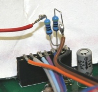
WARNING: if you plan to access the PWM mode you MUST make the following change to hardware.
(1) Remove the menu switch wire going to pin 6 of J6
(2) Solder two 470 ohm resistors to pin 6 of J6. (See photo above)
(3) The free end of one resistor goes to the menu wire
(4) The free end of the second resistor, the PWM output, goes to a wire to your speed control system. In my case it went to the motor tag board on the rear panel.
If you do not do this modification and you operate the menu switch during PWM operation you will directly short the PWM to ground via the menu switch and almost certainly damage the PWM port - effectively ruining your 18F4685. YOU HAVE BEEN WARNED.
If you do not use PWM mode and you never switch on this function in Menu item 37 then you will not need the hardware modification.
Drive
I imagine that the amount of drive available from the PWM is quite small - the signal has the limitations of the 470 ohm resistor and as the PWM signal is 0-5volts then only a few mA are available. You will need at least a darlington output transistor to switch a relatively modest motor.
DG5CST has produced this hardware to drive his azimuth motor
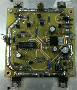
Board for Seb DG5CST motor control using PWM
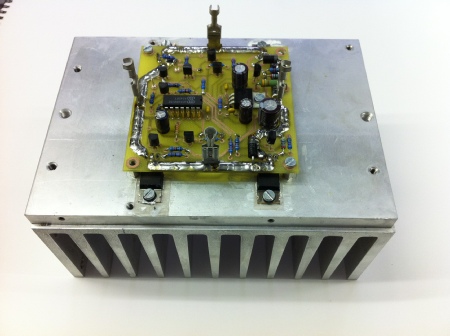
Seb’s Motor driver board on heat sink, note solder on high current traces
Download Eagle files and large photos for DG5CST board
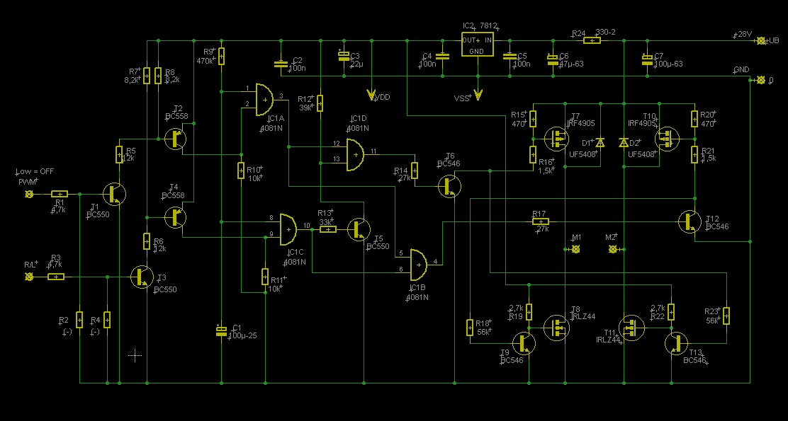
Download circuit of PWM driver (PDF)
| Repeater features |
| Solar version |
| 1750Hz decoder |
| Record and playback |
| Voice interface |
| Micor solution |
| Yagi Calculator |
| RD Contest logger |
| Moon Tracking |
| Orbitron interface |
| PRFCalc |
| TAIT programming |
| Proton Development Suite |
| Old crystals for radios |
| Compound interest |
| Yagi photos |
| Bird proofing |
| Bender |
| VK5DJ downloads |
| VK3UM downloads |
| Site map |