

J.F.Drew © 2000-2017


Mobile menus
VK5DJ
Experiments with a si5351a frequency synthesiser
The si5351a can be programmed to produce a frequency from 8kHz to 200MHz.
The datasheet describes it as:
The Si5351 is an I2C configurable clock generator that is ideally suited for replacing crystals, crystal oscillators, VCXOs, phase-locked loops (PLLs), and fanout buffers in cost-sensitive applications. Based on a PLL/VCXO + high resolution MultiSynth fractional divider architecture, the Si5351 can generate any frequency up to 160 MHz on each of its outputs with 0 ppm error.
The photo on the right shows the very crude prototyping setup but the amazing thing is the output is stable, on frequency and strong.
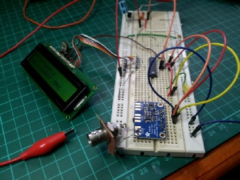
Wow, it works!

I found the si5351a quite complex to get going but fortunately Les Johnson (developer of Proton Basic) converted a ‘C’ solution and the hard work was done.
In the long run I plan to make a simple signal generator to take to hilltop repeater sites. My Marconi signal generator is large and heavy and I don’t like it bumping around in the back of my 4WD.
Several of us on the PDS Forum have used the si5351a module from Adafruit. It is cheap, very stable in its operation and uses little current (around 30mA). It is possible to change the output level via settings of 2mA, 4mA, 6mA and 8mA.
The output is a square wave so is quite rich in odd harmonics. Generally it will be necessary to use a low pass filter somewhere in your circuit although in some situations the harmonics can be used to advantage.
As the micro only has to provide an I2C command almost any PIC(c) can be chosen. The example uses a PIC16F1827 but only because I have a stock of these and the device has an internal clock - saves on a crystal.
Accuracy of the Adafruit module is quite good but it can be easily trimmed by making adjustments to the crystal clock setting in the program (see cXTAL_FREQ ). When you have cXTAL_FREQ right the rest of your frequencies will be accurate. In my case I'm getting within a Hertz or two as measured by my frequency meter. Temperature stability is good despite the simplicity of an exposed crystal.
I have not yet built a circuit board. Experiments have been done on prototyping board. There are numerous references about the need to have a really clean supply to avoid hum. The output signal from my very crude setup is reasonably clean but I can just detect some mains hum. Jitter seems quite acceptable. My final build will use battery power as I plan to make it a portable unit for repeater measurements.
The most basic circuit is a +5V supply, a micro of your choosing, an LCD as an option and the Adafruit board. I've added two resistors to perform a switch function on the project. One switch causes the unit to move up to the next frequency in eedata memory and a down button to move down through the eedata list. Wrap around is performed.
The attached circuit is by way of getting users started, it is not a final project but you should be able to use the program for modifications to your needs. It outputs two frequencies, one on CLK0, the other on CLK1,
It is worth noting that the si5351a supports two ports (one for each PLL) when using integers. To use the third port two of the CLK outs must share a PLL and therefore must be in an integer relationship, alternatively a floating point approach must be used which will result in more jitter. Until I learn how AND need the third, two outputs will be more than acceptable.
I would like to modulate the device but there is no simple way. I'm looking at using a phase modulator out of an old commercial FM transceiver.
In the above screen grab from my spectrum analyser the harmonics of the 7.1MHz signal are quite strong. As to be expected from a square wave output the odd harmonics are especially so but the even harmonics are still easily seen although well down. The sweep is from 6MHz to 100MHz.
The project has progressed - A modulated Signal Generator
The problem was to modulate the signal. In the end I have used the exciter board out of a Phillips FM828 transceiver. The si5351 now acts as the crystal controlled frequency input for the exciter board. The board will lock from 143.1MHz to 150MHz plus. I did experiment with stacking a 70cm FM828 exciter and using two outputs from the si5351 to provide either 70cm or 2m outputs. Unfortunately the 70cm board had a very narrow coverage before lock was lost and retuning was required. As a result I have removed the 70cm board and used the 3rd harmonic of the 2m signal. The downside was that the deviation was also multiplied so this had to be counteracted in software.
The frequency generating hardware now consists of the Micromite Backplane board from Geoff Graham’s Micromite projects. Find his page here. In effect it’s a PIC32MX150F128 chip preloaded with a BASIC interpreter and attached to a touch sensitive graphic display. The BASIC works very well and is simple to program. I have written code for the Micromite that does the following:
1) senses whether the input switch is in the 2M or 70cm position.
2) measures the input voltage and displays it
3) generates a 1kHz tone (square wave)
4) communicates with the si5351 via I2C and sets the frequency.
5) communicates with a digital potentiometer (ds18030-010) via I2C to set tone levels (deviation)
6) displays up to three screens - a welcome screen, frequency entry, and running screen.

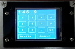
Entry Screen Frequency input Running screen
The Entry screen is on for just two seconds to remind me that I chose 2metres or 70cm. It then goes to the frequency entry screen where the frequency may be entered. On hitting the Go button the frequency is manipulated to the correct crystal frequency (18MHz range) for the exciter board. The appropriate deviation is also selected (e.g. although the 3kHz deviation button is active the deviation may be set to 1kHz (*3 to get the 3kHz deviation on the third harmonic) if a 70cm setting has been chosen.
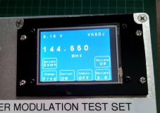
The running screen has 6 soft buttons.
Freq: return to the frequency setting screen
Carrier On: activates or de-activates the carrier
Modulation: activates or de-activates the tone/modulation
Deviation down and deviation up:provide control of the digital pot so that deviation may be increased or decreased beyond the chosen setting for fine control or to check the behaviour of a receiver across the range of deviations.
Preset Deviation: sets for 3kHz, 1kHz or adjustable deviation


Left: view inside the die cast box. FM828 exciter board, in the bottom right is the 5V regulator with the si5351 board and the flying leads plug into the Micromite.
On the bottom wall is the digital pot.
Right: The back of the Micromite Backplane Board. At the bottom can be seen the si5351 board and the 5V regulator.

Right: side view of the sig gen showing the 2M antenna from a WeathAlert (see elsewhere on this site.) The switch is for 2M or 70cm operation.
11-14V power enters through the socket (centre). Later I’ll put three LI-Ion cells inside.
Other issues:
1) because the audio signal out of the Micromite is actually a square wave I installed a three stage passive low pass filter before the digital pot’s input to approximate a sine wave.
2) the FM828 deviation varies as it warms. At present it’s taking an hour or two to settle down on the programmed deviation. As the sig gen will normally be used with a deviation meter this won’t be too difficult to avoid as the deviation can be changed using the Up and Down buttons on the sig gen.
3) the deviation varies as the frequency is changed. Maybe more careful adjustment of the phase modulators would achieve a flatter response. When a problem gets too hard in hardware I just redo the maths in the software to compensate. I’ve got it pretty right
4) the deviation varies with the supply voltage so I have added a LM317 voltage regulator set to 8.1V
Conclusion
I doubt if anyone will copy this project but maybe my experiments will shed some light on the pitfalls of trying to do this.
This project will be used when setting the deviation levels of our extensive linked repeater system here in the South East of South Australia. It is critical that the output levels of repeaters and the links follow a standard. The sig gen will be used along with a tuneable deviation meter to achieve this. My Marconi 2031 Sig Gen has been used in the past but it is big and heavy. As mentioned above I don’t especially like carting it up rough tracks to hilltop sites. This project will achieve the same result and can be handheld and powered by a battery.
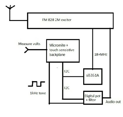
Block diagram of my setup. The digital pot and the si5351A share the same I2C lines.
I have set the address of the digital pot as 40 (Hex28) using decimal 7 bit addressing as I connected the three pot addressing pins to ground.
The si5351 uses an address of 96 decimal (Hex60).
The 3 stage RC low pass audio filter is placed before the pot.
| Repeater features |
| Solar version |
| 1750Hz decoder |
| Record and playback |
| Voice interface |
| Micor solution |
| Yagi Calculator |
| RD Contest logger |
| Moon Tracking |
| Orbitron interface |
| PRFCalc |
| TAIT programming |
| Proton Development Suite |
| Old crystals for radios |
| Compound interest |
| Yagi photos |
| Bird proofing |
| Bender |
| VK5DJ downloads |
| VK3UM downloads |
| Site map |