

J.F.Drew © 2000-2017


Mobile menus
VK5DJ

Sourcing a 148Mhz receiver -The WeathAlert box
The WeathAlert system is a defunct warning system primarily designed for boat safety. Weather information was broadcast on 148.0875Mhz and displayed on a LCD on the Weathalert.
For this project the Weathalert parts used are the box, the supplied BNC rubber ducky antenna and the receiver.
The radio club’s beacon system at VK5RSE - 1296.550, 432.550, 146.550 is located on a hill near my home and directly in line with moonrise at VK5MC’s QTH. We need to be able to turn the beacons off to stop interference. This project will enable Chris or me to turn off the beacons by remote control.
The project involves a 2M link receiver (from the Weathalert) a DTMF decode chip and a PIC© to provide the necessary remote control functions.
The PIC section has yet to be built but will use one of my repeater control boards with parts omitted! With our APRS at the same site we want to control each beacon and the Packet Radio digi too.
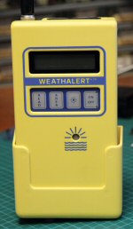
The WeathAlert
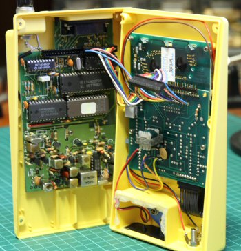
Top left logic, bottom left rcvr Right is display board
The receiver/logic board is removed from the Weathalert and the logic section cut off with a hacksaw. I chose to remove the large ICs at the bottom (HY6116 and 27C64) and cut through the sockets leaving the bottom row intact. This had minimum disruption to the traces and left the receiver intact. The receiver is a sensitive. crystal controlled receiver for 2metres (148.0875 MHz to be exact). The original crystal is on 68.69375MHz. (2*68.69375 + 10 .70 = 148.0875).
Trying various crystals around the shack that might get the receiver into our band met with no success - the oscillator didn't like them. So I changed the feedback capacitor on the bottom of the board by adding a ceramic 82pF cap between the emitter of the oscillator transistor and ground. This gave the necessary oomph to cause some old crystals to fire up. No adjustment of the oscillator tuning was required.
The crystal I used was one for 146.90 RX and I assume it is an overtone crystal probably in the 45 MHz range. Anyway this combination produced an oscillation at 136.3 MHz which when adding the 10.7MHz IF resulted in a receiver on 147.00MHz. Success!
A 0.1uV signal produced an audible tone in headphones, but a nicely saturated signal needed about 2uV. Not bad.
There is no mute wired in these receivers but the IF/Demodulator chip does have the facility. You'd need to read the Data sheet for the MC3357 to arrange this.
Of course no well meaning amateur would settle for leaving the adjustments where they are - so I fiddled with the series inductor (the one near the crystal) and this had very little effect on frequency.
I was able to peak the signal by adjusting the multiplier tank coil. A trick passed on to me by Brian VK5VI is to use a jewellers screwdriver and while holding it in position on the slug warm the shaft of the screwdriver with a soldering iron. Careful judgement and the wax melts and enables easy adjustment of the slug. A good trick to remember.
The crystal socket is soldered to two pins made from a resistor's lead. A pin is soldered (a) into the active hole of the removed crystal and (b) another pin uses the earth hole of the second crystal which is not installed in this model. This was necessary because I used a socket that was too big to go into the original crystal's holes.
A power pin (5-9volts) is created near the end of R15 and an earth pin is added by soldering to the top of the board near TP1. Audio is taken from TP1 and earth. There is another earth pin in the corner of the board near the MC3357.
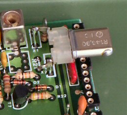
The crystal socket is soldered to two pins made from a resistor's lead. A pin is soldered (a) into the active hole of the removed crystal and (b) another pin uses the earth hole of the second crystal which is not installed in this model.
This was necessary because I used a socket that was too big to go into the original crystal's holes. See photo right:
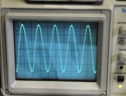
CRO display (photo above) showing a received 1kHz tone from my signal generator. It’s a good strong signal with just a little distortion.
Some experimentation may be needed with the crystal oscillator. I found that the tuning slug on the netting coil made little difference .
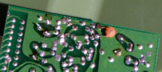
The photo to right shows the positioning of the additional 82pF capacitor.
There you have it - very little work and a nice little 2 metre receiver!
See here for an application for the receiver.
| Repeater features |
| Solar version |
| 1750Hz decoder |
| Record and playback |
| Voice interface |
| Micor solution |
| Yagi Calculator |
| RD Contest logger |
| Moon Tracking |
| Orbitron interface |
| PRFCalc |
| TAIT programming |
| Proton Development Suite |
| Old crystals for radios |
| Compound interest |
| Yagi photos |
| Bird proofing |
| Bender |
| VK5DJ downloads |
| VK3UM downloads |
| Site map |