

J.F.Drew © 2000-2017


Mobile menus
VK5DJ
Using the VK5DJ controller with a MICOR based repeater
John, K7BIT writes about his experiments with a MICOR repeater, a VK5DJ repeater controller and a PI3 to provide HDMI to a 1024x768 touch LCD display, as well as wireless internet, a web server, samba and other features complementary to advanced repeater operations:
I used 2n7000, with 100K pullup resistor to invert PL-IND(drives RPTR-PTT on MICOR) and REC-UNSQUELCH (Mute). Added jumper for reversing polarity. Wanted to keep PIC completely stock.
On MICOR SCM used stock board
Jumpers for SCM
JU-1 IN
JU-2 IN
JU-3 IN
JU-4 IN
JU-5 OUT, Pullup input side
JU-6 OPEN
JU-7 IN
JU-8 IN
JU-9 IN
JU-10 IN
JU-11 OPEN
JU-12 OPEN
Replaced light with LED, makes board run much cooler, use 1K resister in series with LED.
Jumpers for Squelch Board SB TLN8771A1
JU-1 IN
JU-2 IN
JU-3 OPEN
JU-4 IN
JU-5 IN
JU-6 IN
JU-7 OPEN
JU-8 OPEN
JU-9 IN
JU-10 OPEN
JU-11 IN
JU-12 IN(MUTE)
Mods to SB
Cut following pins at connector from signal path
2
3
4
7
8
9
13
15
18
19
21
22
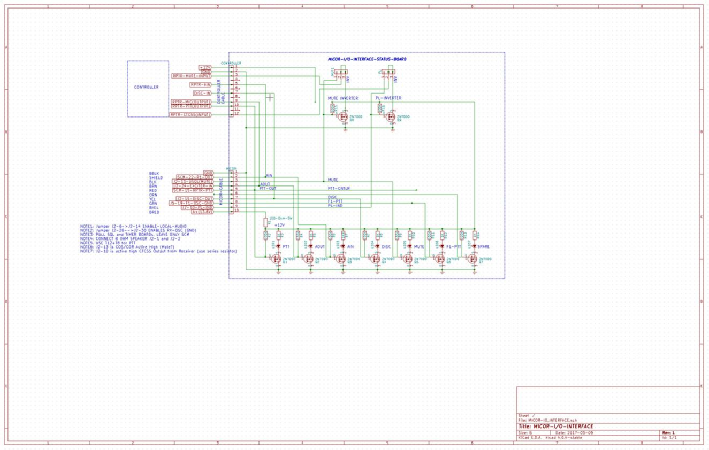
TLN5644A mother board
P2-6-->P2-14 Local Audio, need to hook speakers up to P4-1 and 2, and if LOCAL SPEAKER (EARPIECE) P4-5 and ground.
P2-30 R1-OSC-GND should be connected to ground.
See schematic for correct interface pins and cable construction.
I built a monitor board with 27 2n7000 switching LEDs, was very helpful in determining state and correct polarity for MICOR.
MICOR repeaters are full of floating unterminated inputs, very poor documentation so customer beware. However once all the stuff is correctly fixed your board works great.
Here is picture below of PI3 mounted in case that holds matching 7" touch LCD. That will be base of the unit. I may build a 19" rack panel version so it fits in the MICOR chassis.
2nd picture is the M3008 8 ch 10bit ADC prototype, setup for reference of 3.3VDC reference, then we use external simple voltage divider x 8 for specific measurements. Codewise we have basic display of voltage, will later add complete setup of threshold comparisons to insure overall system is in center of safe operating area, we have real time fwd and rev SWR, PEP power at exciter and transmitter, all the MICOR system measurements for complete system monitoring package. Will be tinkering to connect Pic to PI 3 via serial, SPI or I2C interface. Then work to setup so we can push and pull parameters on the PIC side with the PI 3.
Down stream PI 3 has IRPL, Echolink bits, that we will explore then port to the PIC interface.
I like this solution as the PIC carries the real time load much better than the Pi 3 which is fast but linux, the Pi provides both HDMI and 1024x768 touch LCD display, as well as wireless internet, a web server, samba and other features complementary to advanced repeater operations.
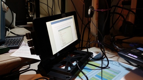
PI3 in case with 7” touch screen
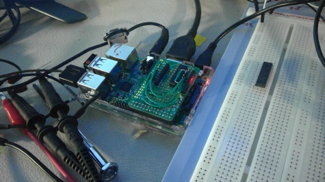
M3008 8channel 10 bit ADC
See text above
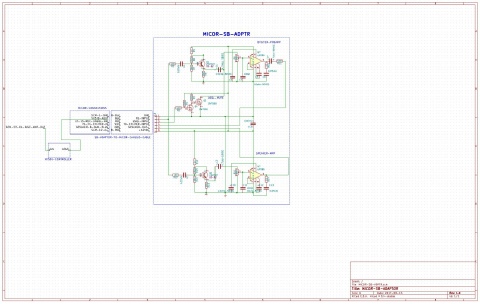
MICOR-SB-Adapter (right)
Further experiments from John
I am working on building a cleaner audio section for MICOR so I can replace crappy SQL board. This drives local speaker for monitoring, and has gated via REC-UNSQL-IND, MIC-OUTàEXCITER-INPUT.
If I was going to build a board, I would merge your controller, this and the previous schematics. I am looking at outright replacing SCM as well. Still tuning this MICORs are very noisy bus wise so may add some inductors to kill off HF noise. Still testing that. The trim pots allow precise control of output levels. NOTE: I use AIN(controller input) and AOUT(RPTR-OUT).
| Repeater features |
| Solar version |
| 1750Hz decoder |
| Record and playback |
| Voice interface |
| Micor solution |
| Yagi Calculator |
| RD Contest logger |
| Moon Tracking |
| Orbitron interface |
| PRFCalc |
| TAIT programming |
| Proton Development Suite |
| Old crystals for radios |
| Compound interest |
| Yagi photos |
| Bird proofing |
| Bender |
| VK5DJ downloads |
| VK3UM downloads |
| Site map |