

J.F.Drew © 2000-2017


Mobile menus
VK5DJ
Mk 2 Repeater controller - August 2017
A linking three way controller
Introduction
 Primarily designed to work with the TAIT remote station modules this controller provides complete management of one duplex repeater and two associated radio links. It is anticipated that the completed repeater station would sit between two other sites receiving and supplying audio of a fixed level (-10dBm) from/to both linking units thus simplifying the setup processes.The unit will replace a VK5DJ Repeater Controller Mk1 (with only one linking port) and its associated audio circuit.
The key design goals were to achieve ease of setup, flexibility and useful options.
The common point of the audio mixer is available on connector CN6 to facilitate either a CRO or other level monitoring. The audio stages are designed to mix the various signals without affecting load impedances. The intention is that -10dBm input on any of the 5 inputs to the audio stages will result in -10dBm output on all the outputs of the audio stage. This design uses top cut filters on the PIC pins presenting beeps/callsigns/messages as good sine waves. There are level controls for the CW output, the 1kHz test tone and the CTCSS and DTMF decoders.
The absence of other level controls is intentional, the TAIT receivers and exciters have line level controls so the audio section provides mixing only. The audio bridge portion is designed to work with audio in/out at -10dBm with 600 ohm load.
The controller manages the PTT of the main repeater and associated radio links. Each transmitter can be enabled or disabled, and control of TX functions can also include CTCSS control.
Timeouts are fully flexible on main timeout (mins), callsign (mins), length of tail, presence of courtesy tones etc. etc.
Three callsign modes are supported.
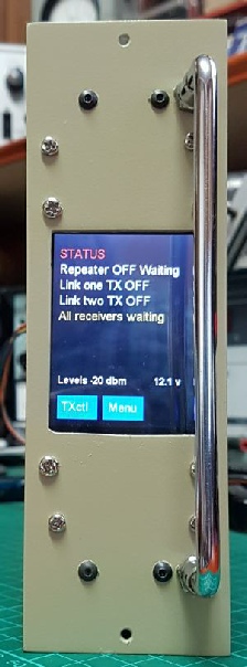
The setup can be managed by DTMF and/or locally using a touch keypad on a 320*240 graphic LCD. The latter controlled by a PIC18F25k22 as a slave from the main controller PIC18F2480. A useful addition to the DTMF controls is the capability to change the password from the keypad.
A complete list of functions is shown later in this document, see below.
To ensure correct sequencing for simplex links the controller, on receipt of a COS, provides outputs (active low) to disable the inactive receivers. For example an input on the Repeater receiver disables the two link receivers, then activates the two link transmitters (assuming they are enabled in settings). On loss of repeater receiver COS the transmitters are first shut down then the receivers are activated. There is no de-activation of the repeater main receiver as it is a duplex system and local input always has precedence over the links.
A Watchdog timer operates in the controller and protects against lockups. It is set for one minute. If for some reason the system crashes the watch dog timer will reset the controller and reload settings from EEDATA storage. There is also a safety mechanism for the graphic display. If by accident it is left in other than display mode it will automatically return to display mode after ten minutes. The screen blanks after 10 minutes of no use to protect the LCD. A touch brings it back.
Summary of features
- Repeater port plus two links
- Setup controlled by either 320*240 touch screen graphic display or DTMF from remote.
- Adjustable timeout which may be inhibited by remote control or CTCSS.
- Adjustable callsign timing including no callsign, preset time and the 15/3sec mode. All callsigns occur at the end of an over.
- Normally CW callsign but supports voice call announcement.
- Voice is recorded ‘over the air’ by remote DTMF control
- Message feature in voice. Plays back a recorded off air message 100 minutes after last COS operation of repeater port. Used for advising of club meetings etc. The idea is to avoid interrupting QSOs.
- CTCSS on board with FX365. CTCSS frequency locally settable from keyboard or by DTMF. This facilitates a change in CTCSS frequency policy.
- CTCSS may be used to enable any of the ports or access a timer cancel feature for broadcasts (port enabling or timer cancelling are alternatives and are mutually exclusive).
- Complete control (excluding record function) of features from local keyboard including DTMF password.
- Factory reset supported (excludes call and password) if you lose track of settings.
- Inhibit links and repeater PTT
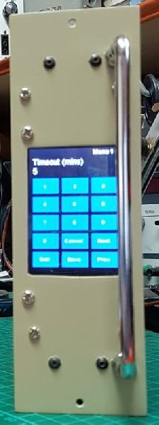
- One add on board controlled using I2C from the mainboard interface manages the touch screen display and the record/playback board (message/callsign voice functions). The touch screen displays active functions including supply volts and audio levels (main screen), a control screen where transmitters may be independently controlled and a test tone sent, and a third menu screen which enables alteration of all 38 internal functions e.g. time out, callsign, CTCSS, active ports etc etc.The controller works without these additional boards but they add useful features and operating ease when on site.
- Access to programming pins of the 18F2480 to enable ICSP update of the program.
- Anti-flutter available to minimize chopping on mobile signals.
- Each COS may be set for a delay before opening. Useful to dodge noise blips.
- Supports three callsign modes. 0=Normal which provides a callsign at the end of overs when the callsign timer rolls over, 1= 15 second silence mode which will not ident unless there has been at least 15 seconds of no triggering and then 3 seconds of continuous carrier. This latter method prevents callsigns when button pushers are active. Thirdly, 2= callsigns prevented entirely.
- Voice is supported –Jaycar Multi-message recorder and cheap single message ISD1820 boards are supported. The latter only supports one message which can be used for either callsign or message depending on settings. Other message boards will probably work. Recording is completed ‘on air’ following a DTMF command.
- Measurement of supply voltage supported. Value appears in CW on tail replacing beep when remote controlled on. Accurate to 0.1 volt after calibration.
- Set low and high battery voltage limits. Above High Volts normal operation, between Low Volts and High Volts a descending three tones on tail, below Low Volts the transmitters are inactive to protect backup battery. An Over Voltage alarm is settable and puts ascending three tones on tail.
- Controller will send 1kHz tone for 30 secs at -10dBm for transmitter level adjustments.
Design and construction team: Download circuits and hex
- Software and logic circuit design John VK5DJ
- Audio section design and assembly into trial repeater Brian VK5VI
- Drawing of circuits, fault finding and hardware design and controller construction Barry VK5BW

Brian VK5VI John VK5DJ Barry VK5BW
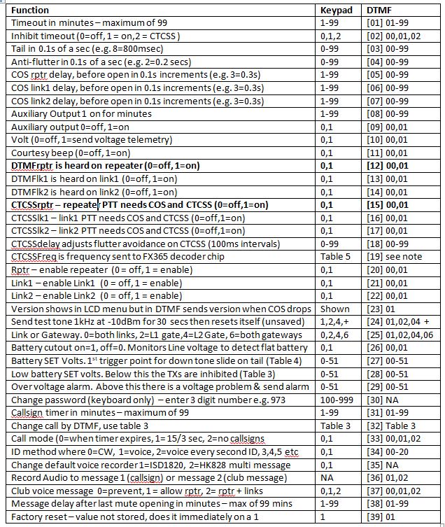
Summary of commands for the Mk2 Repeater Controller
Commands may be sent by remote DTMF or locally from a touch screen. The item numbers are identical for both methods but only the keyboard may change the password and the type of voice recorder while only the DTMF system may begin a recording session. DTMF assumes that a password is sent first with a star prefix. Example *987. In the command/function list square brackets indicate the function which is then followed by the data.
All DTMF commands and data use two digits e.g. 01,02,03,....99. Here is the Table 2 summary.
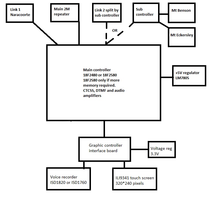
Above: An overview of how VK5RMG is setup. An expansion board has been fitted to enable 3 link ports to be used. The expansion board splits the Link two port on the main controller into two - providing an additional port. Normally the controller would be limited to two ports. The expansion board is a separate project and is located in an additional chassis at VK5RMG.
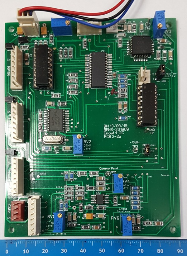
The main board:
1) power to 5V regulator at top with programming to right.
2) on left the interfaces from top: Repeater, Link1, Link2,, Red I2C out and audio inside.
The opto couplers are in sockets so that in case of damage in the outside world the chip can be replaced. Experience talking.
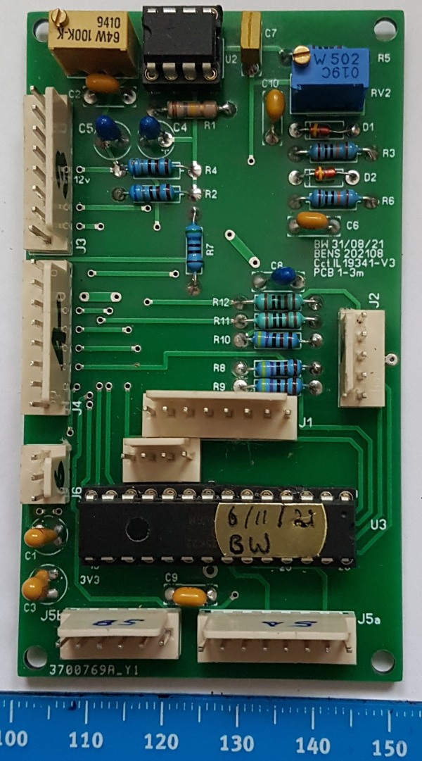
The graphic and touch controller.
This board also measures the 12V supply to provide the onscreen voltage readout.
J1 spare connector for expansion.
J3 input from main controller
J4 is the connector for the audio record board if used.
J5a/5b connector for the graphic 320*240 display with touch.
J6 3V3 voltage regulator
| Repeater features |
| Solar version |
| 1750Hz decoder |
| Record and playback |
| Voice interface |
| Micor solution |
| Yagi Calculator |
| RD Contest logger |
| Moon Tracking |
| Orbitron interface |
| PRFCalc |
| TAIT programming |
| Proton Development Suite |
| Old crystals for radios |
| Compound interest |
| Yagi photos |
| Bird proofing |
| Bender |
| VK5DJ downloads |
| VK3UM downloads |
| Site map |