

J.F.Drew © 2000-2017


Mobile menus
VK5DJ


This page describes my beam controller project
A few boards are available from VK5MC

Beam rotator controller - updated to 12.8.1(4 line) on 15 Jan 2025
The purpose of this project is to present a PIC© based project for accurate manual or automatic tracking of a dish/beam.
The project has built in accurate sun and moon tracking, but may be optionally interfaced to a computer for satellite tracking (Orbitron software) and for EME Doug McArthur’s (VK3UM) AutoTrack software. The unit supports GPS setting of date/time/lat/long for field work.
Features are extensive. Click here for a summary.
The project supports a variety of direction encoders including: an AS5040/AS5045 magnetic absolute encoder chip; MA3-P12 device and SEI system for A2, A2T from US-Digital; HH-05 and HH-12 from DF1SR, Screwjack output; potentiometer output; 16 bit Gray Coded wheel; SCA61T inclinometer chip for elevation and now a magnetometer.
The beam/dish controller unit - how does it work?
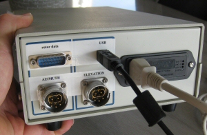
There are two main parts to the project. At the antenna the AZ/EL boards communicate with encoders that provide the absolute position of the antenna system. The AZ/EL boards are polled (9600 baud ASCII) by the Shack Unit to gather the antenna position information. In addition the Shack Unit computes the position of the moon/sun, then decides which way it should turn the antennas to track depending on north/south stops. The shack unit may also talk to a computer or a network.
The 18F4685 in the main shack unit converts the number stream from the antenna to degrees of movement. A third serial stream may be established with a computer providing information on the location of satellites or alternate Moon information. Alternatively this serial stream may connect to the Internet using a WIZ110SR (serial to network adapter) for remote operation.
Because moon and sun tracking software is contained in the PIC© program the system is a self contained unit. All the direction control is managed within the unit. An external computer is not essential. Because the sun's apparent motion is much easier to calculate, the sun routine produces results within 0.01 degree of the Astronomical Almanac. The latter is useful for direction calibration purposes using shadows or sun noise. The moon calculations are usually accurate to < 0.1 degree but there may be variations up to 0.2 degree. A similar result to many other tracking programs. I use the program AA.exe as a reference.
The preferred PIC for the shack unit is the 18F4685 (90KB of memory) . The advantage of the bigger chips is that I have been able to add extra features including a more accurate doppler calculation and add support for the SCA61T inclinometer chip from Version 8.00. All chips are pin for pin compatible, no hardware changes are required from earlier versions.
I have developed a capability so that a satellite tracking program that outputs the right data (Az and El for the satellite) will be able to control the beam. See this page for further information on my Orbitron interface.
Construction: the boards are double sided, plated through, screen printed. The components used are traditional through hole parts. This suits my supply of parts and my shaky hands with a soldering iron! I have sets of bare boards for sale. See the Contact Me page for details.
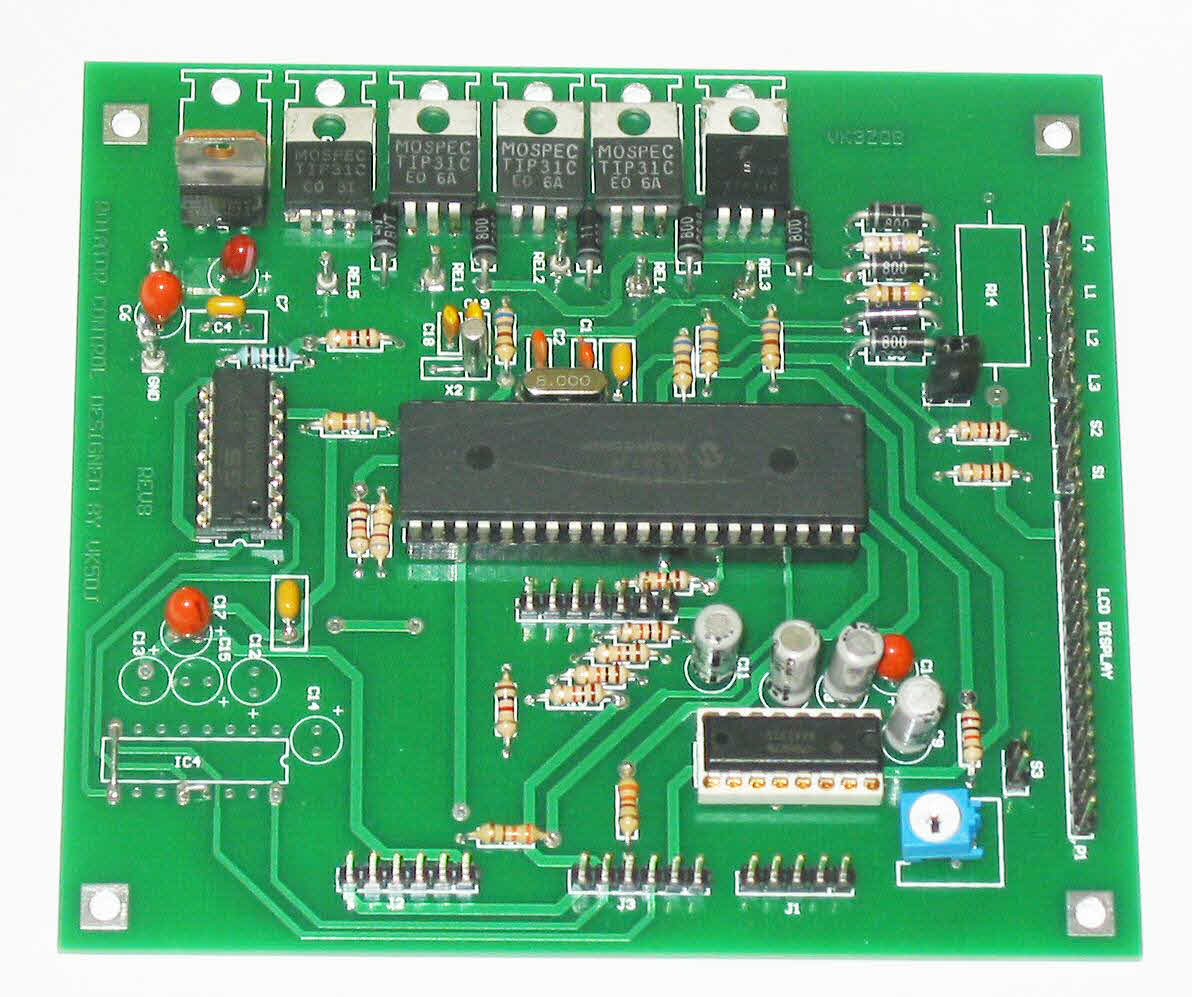
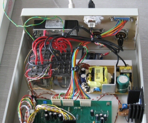
The main board in the shack unit is shown bottom/left. I used 1A output transistors to switch the antennas but depending on your needs these may be small signal types. For example if driving a Yaesu G-5500 satellite system you would not install relays and use small signal transistors to switch the logic level in the G-5500 control box. My system switches higher current so I use relays. See photo of my 2 liner version.
See the downloads page for the manual and HEX files updated 15/01/25 to Version 12.8.1 with fixes to Park, new LCD driver, etc see readme1st.tx
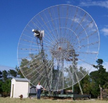


Chris VK5MC 10metre dish
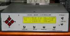
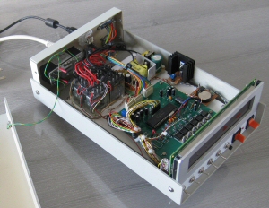
The 4 line VK5DJ controller
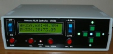
Stan LZ2STO great looking 2 line LCD
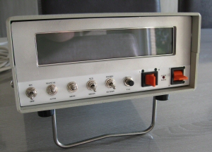
Top view of my 2 liner version
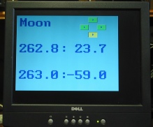
Micro-VGA display to monitor
The AZ or EL circuit board
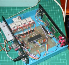
Main board in shack unit- click for larger
Christer Grannsjo, SM4FXR, with the 16 bit encoder described on the 16 bit page.
Shack unit options
There are three main options for the main unit that require different HEX code to be loaded.
- Two line display shows AZ/EL of the antenna and AZ/EL of the object. An internal software clock needs to be reset on power on
- Two line display as above, but uses a battery backed DS1307 hardware clock from Futurlec.
- Four line display with hardware clock. The 4 line LCD also shows declination of the moon, doppler, UTC and local time.
All displays indicate if the internal swap direction delay is operative. The 2 line displays may be set to show brief displays of doppler and time.
There are 42 menu items to set the unit for the conditions you require. The menu items are described fully in the manual for the project.
The shack software permits three inputs
- ASCII from the AZ/EL unit (interfacing to either a digital encoder or a PWM encoder)
- Analogue voltage 0-5V from a linear potentiometer OR an AS5040/45 or other encoders running in analogue mode.
- Computer or Internet via a WIZ110SR
Photos below of construction by Kevin Scheveneels
| Repeater features |
| Solar version |
| 1750Hz decoder |
| Record and playback |
| Voice interface |
| Micor solution |
| Yagi Calculator |
| RD Contest logger |
| Moon Tracking |
| Orbitron interface |
| PRFCalc |
| TAIT programming |
| Proton Development Suite |
| Old crystals for radios |
| Compound interest |
| Yagi photos |
| Bird proofing |
| Bender |
| VK5DJ downloads |
| VK3UM downloads |
| Site map |