

J.F.Drew © 2000-2017


Mobile menus
VK5DJ


Repeater linking controller
General features include:
Two port linking repeater controller design for amateur or professional use - usually a duplex repeater on port 1 and a simplex link or gateway on port 2.
As well as the conventional morse ID via a morse code callsign, the controller can also operate in beacon mode to deliver a short morse message at a programmable interval. All timers are remote configurable by DTMF as is the callsign and a CW message facility. CTCSS access is provided. The key to the project is the PIC16F1827 microcontroller. The latest HEX file is available free from this site. Click here for a summary of features.
The main download is a set of document files, parts list, photos, GERBER files for board manufacture, hex file for loading the PIC and PDFs to assist readers in the building of a repeater controller.
All boards sold. I do not plan to have more made but continue to support the software.
Interface issues
The connection to the Carrier Operated Switch (COS or mute) of receivers can vary considerably from radio to radio. Here is some advice that may save some frustrating moments.
(1) To ease changing COS polarities:
When wiring R21 and R22 stand the resistors on end with the resistor body in the R21, R22 resistor holes closest to the centre of the board. Bend the long top lead so that it may be soldered into the correct hole near C9. The hole closest to C9 connects the resistor to +5V whereas the inner hole connects it to 0V. If at a later date you need to change polarity it is easy to snip the long resistor tail and bend it out of the way. A new wire can then be soldered into the alternate hole and soldered to the remaining tail of the resistor. Alternatively resistors R21 and R22 could be left off the board entirely and wired externally. Board photos on this site do not show these suggestions.
(2) To cater for different COS situations use Table 1 in association with the manual:

The controller is in the left slot of this TAIT converted commercial repeater now on 2 metres
(3) Note that when using open collector COS equipment in the positive active mode it will be necessary to tie an unused simplex port COS to 0V. This is most easily done on the back of any input plug to the controller. If this is not done the software will think the COS is active. In this mode if the main receiver is turned off the controller will interpret this as a received signal and key the transmitter. In all other modes the controller will ignore loss of receiver power and not key the transmitter(s).
(4) To cater for different PTT situations see Table 2.
(5) Note that the circuit diagram shows capacitors C14,15,18,21 with negative to the outside world. Some radios have +ve voltage on their microphone inputs. This will result in distorted audio and possible failure of the capacitors. I strongly suggest these capacitors are wired with +ve to the outside world. The circuit is wrong as is the board overlay.
Single sided board for homebrewers
I have been approached by people regarding a single sided board version of the controller. Santiago P. Sison Jr. has developed a single sided board for the 16F84 version and this link downloads photos of his work. Santiago is willing to send more detail on request. Read the included santiago.txt for details on how to contact Santiago.
Download single sided info including 16F84A code.
[Note that the 16F84 code is no longer supported]
Using an 8870 for DTMF
If you are unable to get an MC145436 (I have some for sale) you can make a small sub board to plug in an 8870. The 8870 has 18 pins compared to the 14 of the 145436.
I have received information from Arrio IW6BFE and Pisti YO2LYN on how this conversion can be done. Thanks Arrio and Pisti.
Download the ZIP archive"8870.zip". This conversion is provided by Arrio IW6BFE.
Pisti YO2YLN has pointed out that the 8870 has a latched output that holds the last code. In the old 16F84 program this created a decoding problem, but with the 16F628 program using the link on the rear of the board to feed DTMF detect signals this is overcome. Pisti will provide another version of the 8870 circuit as soon as he has completed tests.
I've recently had a message from Arrio IW6BFE that when experimenting with a 8870 he did not get enough drive from the clock output of the 8870 to the clock input of a 16F628. He does not know if he just has a bad 16F628 (worked fine with the 16F84) or if the 8870 output is marginal. The symptoms were a non functioning controller that could be made to sometimes work by placing a finger on clock pins. It might be that Arrio has a crystal that is a little down on activity. I post this here in case anyone else has problems. Note that a change to a 16F1827 fixes this problem.
Here are Arrio's comments regarding the earlier versions:
“The problem is related to not enough clock signal coming from the 8870 oscillator, with standard components it is around 1.2 Vpp, by removing the 1 Mohm resistor parallel connected to the crystal (not critical), and putting a 10nF capacitor parallel connected to C6 (33pF), now the circuit is working fine.”
Arrio has written an Italian language project description for the old repeater controller.
See the Downloads page for all files and documents.
Version 6.50 is the latest version for 16F628A while Version 7.10 uses the new PIC16F1827.
NEW: March 2015 controller supports voice ID , reset of all commands to defaults and send version
NEW: August 2015 provides fan control

Table 2: PTT options see note 3
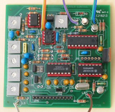
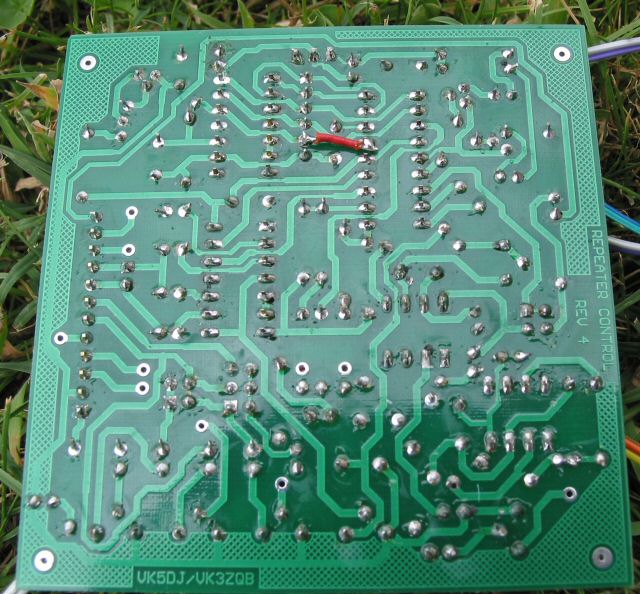
See left for position of additional link required on the bottom of the controller board to cater for new 16F628A code. It connects the valid tone detect from the MC145436 on pin 5 of JP1 to pin 15 of the 16F628A.
Click for larger photo.

Table 1 above: Connecting COS for different polarities
The populated board. I no longer keep a stock of these boards - all sold 1 May 2018
Other amateurs have built versions of the controller and are willing to share their diagrams and gerber files.
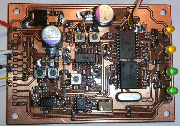
I like the SM approach, let’s face it, it is more modern. If there is ever another version from me I will probably use SM, however I still have many leaded components to use so it may be a while. Here’s a board made by Mats SM0RJV. Mats has offered to provide Gerber files on request. Later they will be put on this site. Mats is still experimenting, the missing components at bottom right are zero resistance resistors as jumpers to select different functionality. He’s making a nice job of his single sided board (groundplane bottom).
| Repeater features |
| Solar version |
| 1750Hz decoder |
| Record and playback |
| Voice interface |
| Micor solution |
| Yagi Calculator |
| RD Contest logger |
| Moon Tracking |
| Orbitron interface |
| PRFCalc |
| TAIT programming |
| Proton Development Suite |
| Old crystals for radios |
| Compound interest |
| Yagi photos |
| Bird proofing |
| Bender |
| VK5DJ downloads |
| VK3UM downloads |
| Site map |