

J.F.Drew © 2000-2017


Mobile menus
VK5DJ
The North East Radio Group Transistor Tester originally from Garry Morton M1GRY
Weathalert units were a commercial product designed to provide weather warnings to fisherman and others. Transmitters were located at strategic places around the coast and the device was continually updated with weather information.
For some reason the project was discontinued and large numbers of these boxes became available. The box contains a 148MHz receiver, various ICs for decoding the data and an LCD. The first project uses the LCD and many of the parts reclaimed from the board to male a transistor tester.
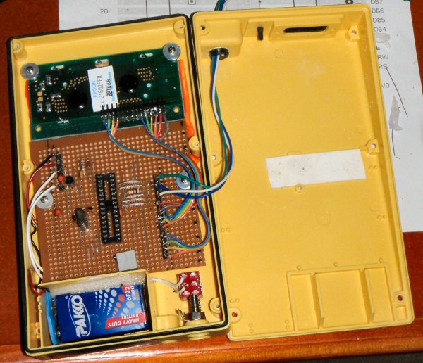
I added a 9V battery and a switch to the front panel. The case and the LCD are ideal for the job. The North East Radio Club have many of these units on hand.
The transistor tester inside view
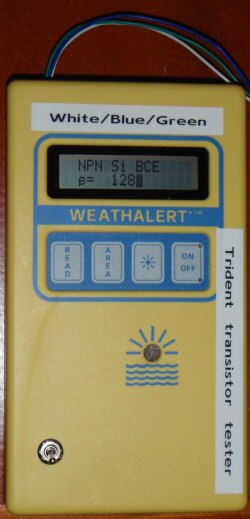
Finished tester -BC548 on test
The tester was described in Practical Wireless of August 2009. Brian VK5VI did the Veroboard layout on behalf of the North East Radio Club. Here is a zip file with the relevant information.
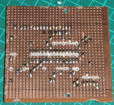
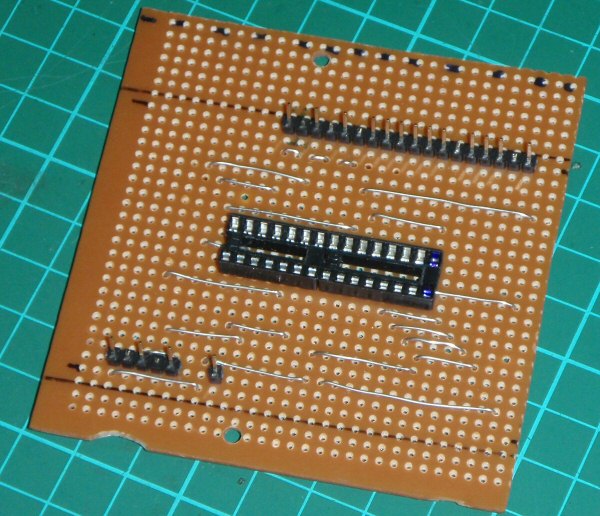
When cutting away the traces on the veroboard use the Flip.jpg which is the view from the bottom of the board and will make it easier to get the gaps in the right spot. When adding the resistors R6,7,8,9,10,11 be aware you need to put some links in first. Before soldering the socket install the links that go under the socket. When the resistors are installed ensure that the leads do not foul the links, if necessary install the resistors a small distance above the veroboard. A 28 pin socket for the PIC is recommended.
I recycled a lot of the parts, this included the crystal from the WeathAlert, the bypass caps, the 100K pot. I installed the pot the reverse to the instructions as I wanted to be able to adjust it easily.
So far it has taken me about 8 hours. The software is identical for any of the recommended PICs so even though the hex code is labelled for the 870 it works in the 876A. Many thanks to Gary for developing this project and sharing the details.
LCD Connections
The connections on the LCD are from bottom to top, That is pin 1 is closest to the centre of the LCD (it is marked on the other side)
Pin - Symbol - I/O Function
1 Vss - - Power supply (GND)
2 Vcc - - Power supply (+5V)
3 Vee - - Contrast adjust (VO on the layout diagram)
4 RS -- reset
5 R/W -- read/write
6 E -- Enable signal
7 DB0 -unused
8 DB1 -unused
9 DB2 -unused
10 DB3 -unused
11 DB4
12 DB5
13 DB6
14 DB7
Showing the top jumpers
The drill hole pattern
| Repeater features |
| Solar version |
| 1750Hz decoder |
| Record and playback |
| Voice interface |
| Micor solution |
| Yagi Calculator |
| RD Contest logger |
| Moon Tracking |
| Orbitron interface |
| PRFCalc |
| TAIT programming |
| Proton Development Suite |
| Old crystals for radios |
| Compound interest |
| Yagi photos |
| Bird proofing |
| Bender |
| VK5DJ downloads |
| VK3UM downloads |
| Site map |