

J.F.Drew © 2000-2017


Mobile menus
VK5DJ
Magnetometer encoder
Over the years I have had a few requests for magnetometer support. At last I’ve done something about it.
There are accuracy limitations for the inexpensive magnetometer, but like all things, how useful depends on how the unit will be used. This project would make an ideal companion to the SCA61T inclinometer elevation encoder.
Accuracy of the economical encoders is of the order of a couple of degrees, although repeatability is closer to 1 degree while readout provides 0.1 degree increments.
The trick is to NOT confuse accuracy with readout or repeatability.
However for two metre or 70cm operation with antennas with a 3dB beamwidth of 5 degrees or more the magnetometer can be a real solution. Especially if you can sight the moon (or sun) aim the antenna at it then press calibrate on the main beam control unit for it to successfully track for some hours.
The magnetometer was chosen when Steve Silverman (KBSII) sent me a sample of the HCM6352. The data sheet is here.
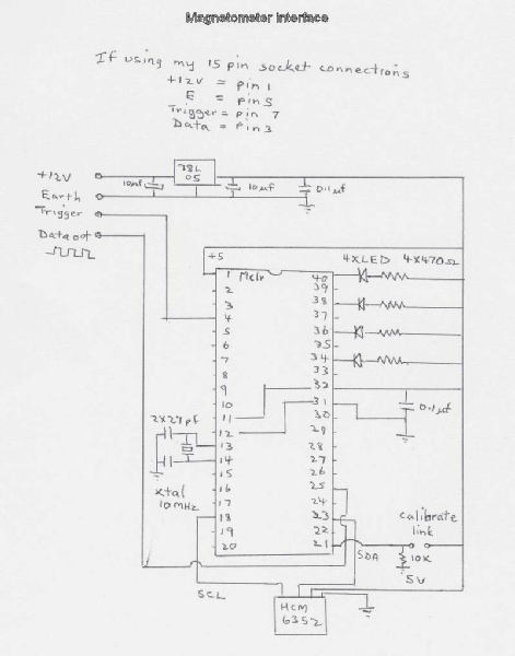
To use the HCM6352 I have made a simple board using veroboard and a 16F877A to communicate with the beam controller unit. Early experiments with the 16F628A in the AZ/EL unit were not successful due to a software issue which is still to be tracked down. Maybe one day I will get it going but in the meantime the 16F877A has an inbuilt I2C MSSP module and as it was easy to use that was my choice. The 16F877A is a bit bulkier being a 40 pin device but it works and is readily available.
How does it work?
The HCM6352 outputs a heading of two bytes over the serial bus about 6mS after it receives the “A” command. The HCM6352 also supports a calibrate function. I have catered for this by adding a jumper option. Putting a jumper on and then powering up causes the HCM6352 to go into calibrate mode. In my program I have set this for 30 secs. While in calibrate mode all 4 LEDs are lit and the user should rotate the sensor two whole turns as smoothly as possible within the 30 second window. During this process the HCM6352 takes account of other metal objects which may be distorting the field and saves the information internally.
The device then returns to read mode leaving just one LED lit indicating the current quadrant. Once the device is calibrated the jumper should be removed and only replaced when the sensor is in a different location or with different surrounds.
The 16F877A communicates with the main controller via 9600 baud, 8 data bits, 1 stop bit, no parity in the same manner as most of the other encoders.
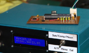
Above top
With beam controller set on Azimuth only on a serial port of 12 bits it reads the current position as 343.10 degrees.
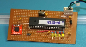
Above bottom
Showing the top view 34 by 18 holes. There are a few jumpers. The compass chip can be seen to the left. I tried some experiments with the HCM6352 dangling on some wires but there seems to be little if any difference in the results. So it seems the position is non critical.
Even small rotations away from the horizontal plane change the reading considerably. I recommend a bubble level is used to keep the HCM6532 readings consistent..
Download the circuit here
Download the hex file here
Purchase the HCM6352 from Sparkfun or perhaps a Robot shop
| Repeater features |
| Solar version |
| 1750Hz decoder |
| Record and playback |
| Voice interface |
| Micor solution |
| Yagi Calculator |
| RD Contest logger |
| Moon Tracking |
| Orbitron interface |
| PRFCalc |
| TAIT programming |
| Proton Development Suite |
| Old crystals for radios |
| Compound interest |
| Yagi photos |
| Bird proofing |
| Bender |
| VK5DJ downloads |
| VK3UM downloads |
| Site map |