

J.F.Drew © 2000-2017


Mobile menus
VK5DJ
YAESU rotators - G5500
+
=
There are several ways you can interface to the Yaesu rotators.
Method 1 (preferred because it maintains the safeguards of the Yaesu controller and enables the use of the Yaesu switches)
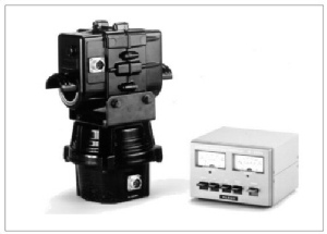
This page reports on how I interfaced to a friend's G-5500 rotator. It will provide clues for interfacing to other rotators.
It is NOT necessary to buy the computer interface hardware - the GS232 costs about $950 in Australia. All you need is in the Yaesu's main control box and the VK5DJ Beam Rotator Project shack unit. The AZ/EL boards are not required.
Do not install the relays in the shack unit. Drive direct from the TIP31s' collectors, use Relay B mode (menu item 37 or thereabouts depending on Version).
Despite what the manual says, the output from pins 1 and 6 of the external control jack is actually 0 to 5V not 2 to 4.5volts. This is a plus as the 0-5V just makes the readings more accurate. If your rotator puts out a smaller voltage range the shack unit can be calibrated to suit.
Note that you should not apply voltages outside the range of 0-5.5V on the AZ or EL analogue inputs of the Shack Unit. The results may be either unpredictable or damage the PIC.
The external control Jack on the Yaesu Controller unit provides all that you need to control your system with the VK5DJ Beam Rotator Project.
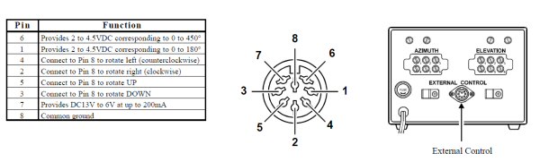
I also powered the Shack unit from the G-5500 Controller unit via pins 7 and 8. It will support up to 200mA and the Shack Unit draws a max imum of 175mA if no relays.
The Youtube video to the right shows the Yaesu unit in operation.
Note that it is also possible to use the GS232 unit with the VK5DJ Rotator Controller but there is simply no point. Before I had access to a G-5500 I did include the control codes in the shack unit software and provided a special menu item. I will remove this functionality in a later version.
There is far more control without the GS232 unit and the money saved can be spent on something more worthwhile.
Wiring: Wire direct from the TIP31C collectors, no relay used. Mode B relay selected in menu item of shack unit. Menu item number varies with the Version of software. See table below.
To have the LEDs work accurately for Mode B Relay operation you need to ignore the LED board connections at L1, L2, L3, L4. Separate wiring is needed. See next section.

I took the cathodes of the LEDs to the appropriate TIP31C - in reality this meant I took them to the large 8 in-line connector on the back of the unit. The anodes of the LEDs I joined the Up/Down together and took these via a single 330 ohm resistor to +5V. I did the same with the Left/Right LEDs joining the anodes and through a single 680 ohm resistor to +5V. Only one resistor is required for each pair as the Up and Down are never active together nor are left/right active at the same time. +5V is available on SW3, it is the pin nearest the board edge closest to RV1.
You do NOT need to use Yaesu mode in the shack unit - just use ModeB relay. The Yaesu codes are not used if you do not have the interface unit.
Menu item 8 should be set for Pot/Pot and the menu items for AZ/EL bits (perhaps menus 25,26 depending on version) should be set for 10 bit for both Az and El. It may be necessary to set Az/El offsets in menu items 12,13 (start with 0). Similarly Az/El spread in items 10,11 may need final adjustment but Az should start with 360.00 and El start with 180.00. Remember the Calibrate switch speeds up the menu display changes but don't leave it on when you exit the menu or it will mess up previous calibrations.
Method 2 of interfacing (not my first choice)
This method just uses the transformer in the Yaesu controller to provide the motor power.You need to extract the power from the transformer somehow, perhaps install a socket.
In this method you connect the Yaesu motors to the relays in the VK5DJ shack unit. One wire from the transformer is permanently wired to the common of the motor windings in the rotator itself. The second wire from the transformer is switched by the Shack Unit relays to either the UP or the Down or for azimuth, the Left or Right. Relay ModeB is used and of course the LEDs have to be wired separately as described above. The wiring of the LEDs on the main board of the shack unit is for ModeA and needs to be abandoned.
The pots in the rotator are connected to the Shack Unit as described in the manual. The Yaesu controller is again bypassed entirely.
I recommend the use of a fuse in the transformer connection. If you make a mistake in the wiring it is possible to short the transformer. Not a good thing.
This method would work fine without any Yaesu controller if an external transformer of the correct voltage and current rating was used.
Method 3 of interfacing (not my first choice)
A variation on Method 2 is to use just part of the Yaesu controller system eg the output of the direction indication.
Personally I recommend method 1. It is the cleanest solution and still enables use of the switches on the Yaesu Controller if you wish.
Click here to download the corrected User Manual for the G-5500 rotator. Update to G5500 connections on 1/5/2014
Note: The above table is WRONG. The table was extracted from the supplied manual. It should read:
3 Connect to Pin 8 to rotate UP
5 Connect to Pin 8 to rotate Down Download corrected G-5500 manual (thanks Dan EI9FHB)
| Repeater features |
| Solar version |
| 1750Hz decoder |
| Record and playback |
| Voice interface |
| Micor solution |
| Yagi Calculator |
| RD Contest logger |
| Moon Tracking |
| Orbitron interface |
| PRFCalc |
| TAIT programming |
| Proton Development Suite |
| Old crystals for radios |
| Compound interest |
| Yagi photos |
| Bird proofing |
| Bender |
| VK5DJ downloads |
| VK3UM downloads |
| Site map |