

J.F.Drew © 2000-2017


Mobile menus
VK5DJ
Large Display
Providing that you do not want to use an external computer to drive the system it is possible to drive a large computer montor providing that you do a bit more work. You will need to purchase a Micro-VGA display system.
The unit used for development was obtained from Dontronics - bt they no longer stock them. It seems that the manufacturer still exists although the module looks different from the one I used it seems to have the same functionality. For that reason I have rebuilt this page. If anyone has trouble getting it going I’m willing to help out.
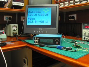
The display hooked up to the beam control system
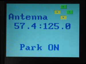
Close up of display in Park mode
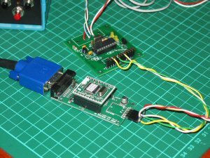
Showing the connection between the modified AZ/EL board and the video display module.
The u-VGA (640*480) video interface takes serial data and displays this on a computer monitor. See the data sheet on the MicroVGA website. For maximum speed I have chosen to use an external PIC interface rather than giving the shack unit more to do - it is busy enough doing its other tasks. The interface I have designed uses an AZ/EL board to do the conversion. An inverter transistor is added to invert the data coming out of the computer interface on the shack unit and remove the -ve going pulses of the RS232. The PIC16F648A (the program is too large to fit in a 16F628A) requires non-inverted TTL data. The converter board communicates with the shack unit at the standard speed of 9600baud while the uVGA device will take a wide range of speeds but in this case I have set the interface to the uVGA at 19200baud. A document describing the interface system is currently being written.
Buttons on the screen indicate the current state of the relays controlling the antenna. If the Park switch is activated the display changes accordingly. In the photo the left and down buttons are depressed. Because I have changed the requirements it is necessary to use version 5.62 software in the shack unit. This will become available when I have finished the documentation.
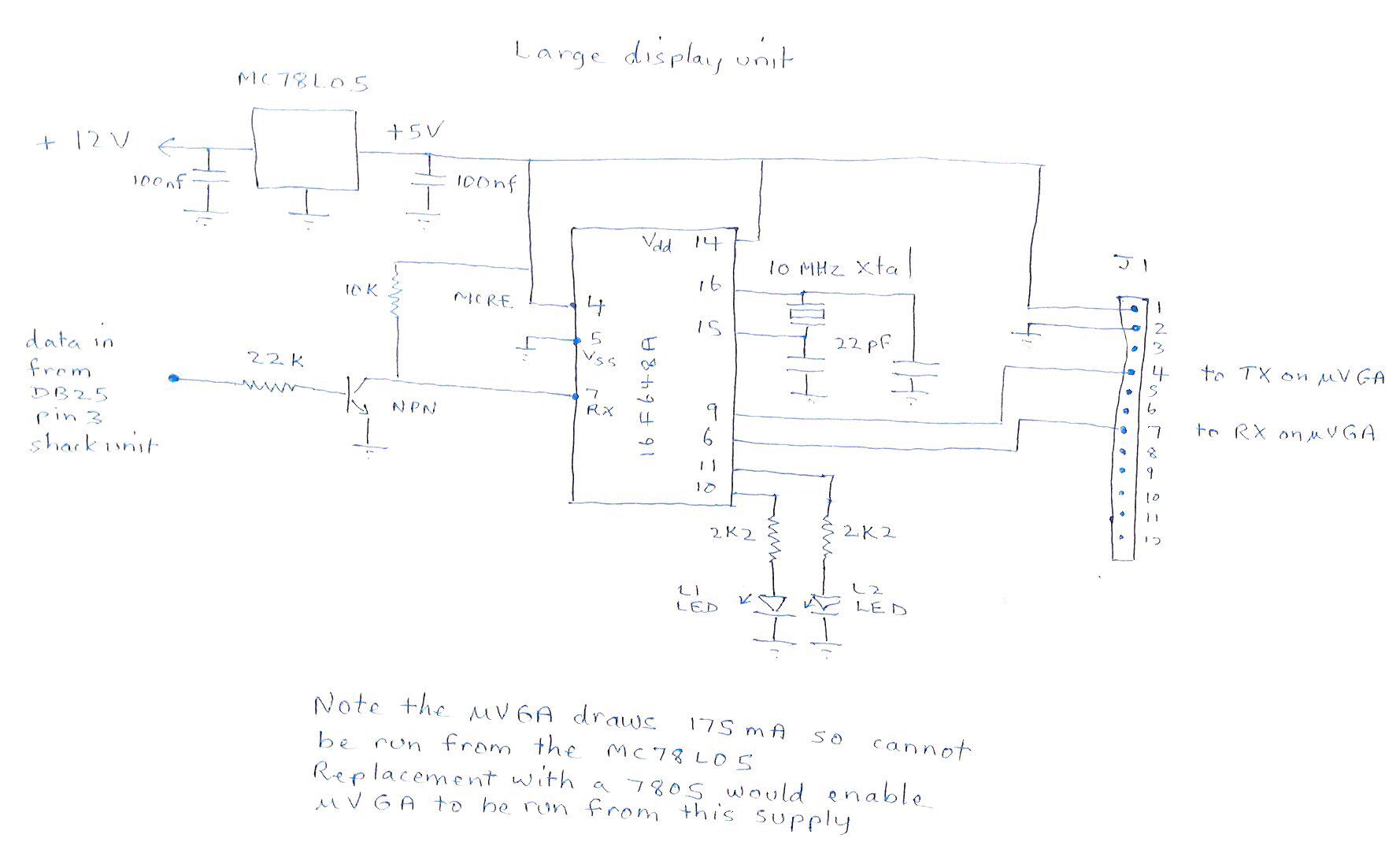
Above: Circuit diagram of modified AZ/EL unit board. Click for larger picture

Modified AZ/EL board top - click for larger image.
Note the 78L05 overlay is wrong. Reverse the 78L05 chip. Also note installation of a small NPN transistor in the LED4/LED3 position. In addition the trace is cut from R4 to pin 8 of the chip. R4 is replaced with a link.
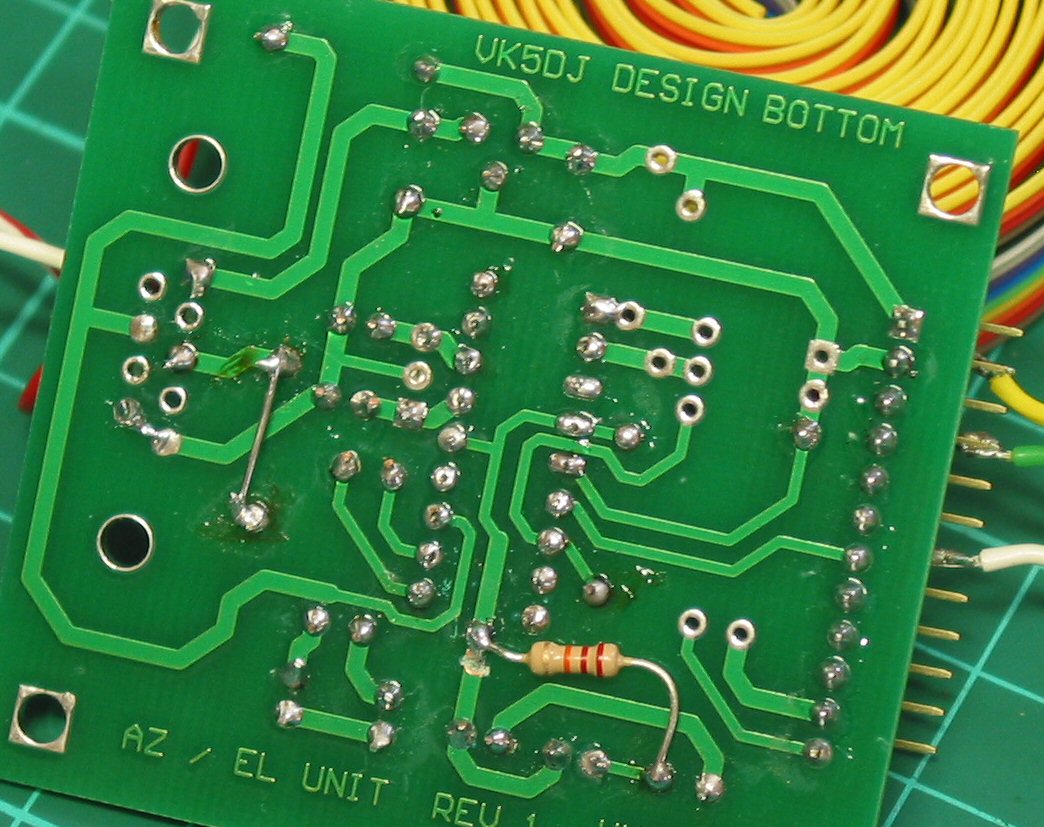
Modified AZ/EL board bottom – click for larger image.
Note: trace cut at left end of resistor to collector of transistor
| Repeater features |
| Solar version |
| 1750Hz decoder |
| Record and playback |
| Voice interface |
| Micor solution |
| Yagi Calculator |
| RD Contest logger |
| Moon Tracking |
| Orbitron interface |
| PRFCalc |
| TAIT programming |
| Proton Development Suite |
| Old crystals for radios |
| Compound interest |
| Yagi photos |
| Bird proofing |
| Bender |
| VK5DJ downloads |
| VK3UM downloads |
| Site map |