

J.F.Drew © 2000-2017


Mobile menus
VK5DJ
Interface to ISD1820 or HK828 voice chips for ID and message
Frequent requests for voice ID have led to further experiments with the controller.
The hard part is that the ports on the PIC16F1827 are almost fully committed.
Due to a change from 16F628A to 16F1827 it has been possible to run the device from an internal oscillator, avoiding the need for a clock input. In addition, the MCLRE pin has been programmed as an input for some years but tied to +5V or used as an AC Fail indicator. This means there are two potentially spare pins - one an input and the other a full blown IO port.
To run a recorder/player for callsign or as a message facility requires a minimum of 3 pins. The solution is to press another PIC into service and communicate with it using either SPI, I2C or ASCII. The last mentioned is the easiest. The additional PIC can be programmed for many ports - a port extender
To connect the two PICs I code ASCII comms at 2400 baud between the main controller unit and the expansion unit. Originally tested at 9600 baud I’ve gone back to 2400 in the interest of reliability. There is no noticeable delay.
Although it is possible to use the two available ports on pins 4 and 16 using bit bashed serial the serious disadvantage is that the code has to sit there waiting for input on receive. On the other hand, using the hardware USART in the PIC it is possible to check for a flag indicating there is data waiting and finish what the PIC was doing then attend to the incoming data when it is convenient. For that reason I have chosen communication using just one byte of information, error checking has not proved necessary although I have used the watchdog (in the external unit) and an interrupt driven timer (in the repeater controller board) to avoid any lockups or comms failures.
In order to make use of the USART two pins have to be freed. Pin 7 (USART receive) and pin 8 (USART transmit).
Here is a description of the modifications to the board.
1. R10 is relocated and placed under the board. It bridges from the plated through hole for R10 nearest Q2 to the vacant hole of C6 nearest the voltage regulator. C6 is not used with the PIC16F1827.
2. The trace between pin 14 and pin 4 is cut under the PIC to free pin 4. A wire is soldered between pin 4 of the PIC and pin 5 of the 567 socket under the board. This modification means that JP3 operates in a different fashion.
3. Pins 1 or 3 of JP3 now provide access to Pin 7 of the PIC (The USART RX in). I used a modified jumper to slip onto these two pins and a wire on the jumper connects to the extender board pic’s pin 8.
4. As the 567 is now permanently wired to pin 4 of the main PIC (the new CTCSS in) if you want to use an external CTCSS detector you would unplug the 567 and install a jumper between pins 2 and 4 of JP3.
5. To provide access to the TX pin of the USART, solder a pin into the unused R10 pin (furthest from the voltage regulator). This pin, when fitted with a suitable clip for access, is the TX out of the USART and will have a wire to the extender board’s PIC’s pin 7 (RX).
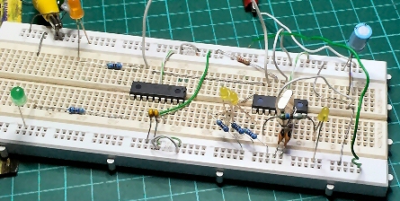
The test setup
The chip to the left is simulating the repeater controller and via its pins 7 and 8 communicates with the expansion port PIC to the right.
LEDs to the right indicate success of commands while the LEDs to the left indicate accurate receipt of ACK packets.
A circuit of the extender is here
Functions now coded into the expansion port PIC16F1827 include:
- Three digital inputs for things such as ‘door open’ or ‘AC fail’
- Two A/D ports for returning a voltage such as ‘battery volts’ or ‘SWR’
- Two spare outputs for things such as ‘antenna switch’ or ‘fan control’
- Record
- Playback
- Record/Playback address (currently Pin 11 is Ident and pin 12 is Message)
Here is a document describing how to modify the repeater controller board including a list of the new remote controls.
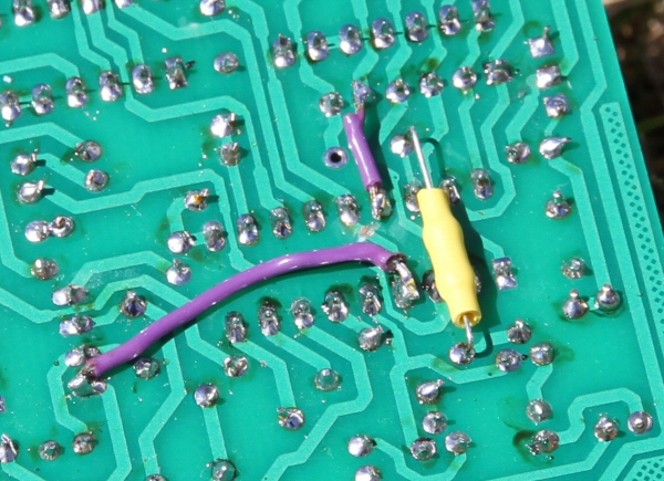
The underside of the controller showing the relocation of R10, a cut to a trace and the additional wires.
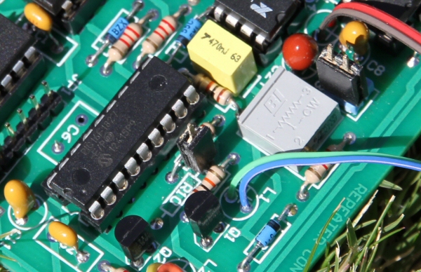
Top of the controller board showing the TX pin (centre) and the RX pin (top right). Although a double clip is shown, only a single is required.
What is supported?
Currently the extender program is setup for two recorders, the ISD1820 voice chip (see Sparkfun) and the HK828 chip as used in the Silicon Chip Magazine Dec 2007 and in the kit (KC5454) from Jaycar Electronics. The ISD1820 has capability for just one message. The Jaycar Kit has provision for up to 8 but in this version can support just two - one for ident and one for a message beacon.
Two different programs are needed in the extender PIC16F1827 to cater for the different recorders.
For the ISD1820 the extender chip outputs a 10ms +ve pulse to start playback after raising a message select pin (not used by 1820). The software then looks for a negative edge provided by the voice chip to finish the playback. Record raises a record pin high during record after enabling the appropriate message select pin(not ued by 1820). Record ceases when record goes low.
In the case of the Jaycar Kit the sequence is quite different. To trigger a playback it was first necessary to toggle the record/playback line low then high briefly to reset the device (not documented), then the message select line is pulled down for at least half a second to initiate playback. During this period the record strobe (LED1) flashes approximately every 500msec. At the end of the playback the strobe stops and this action causes the extender chip to send a message to the repeater controller to release the PTT. Note that a wire has to be taken from the pin 22 (of the HK828) side of the LED to pin 6 of the extender chip. The callsign ident (message 1) triggers pin 11 of the extender chip low while the announcement message (message 2) triggers pin 12 of the extender chip.
The repeater controller does NOT listen when the playback (or a message) is operational, unlike the CW ID which may be talked over. CW ID and message is still available if required by remote control.
To record using the HK828 kit the Record/Playback line is pulled and held low during record and the appropriate message line is pulled low to initiate the record.
The PIC16F1827 is an enhanced device and not all programmers will program them. Programmed PICs are available from the author for $10 each. This version requires all 16F1827.
HEX for Version 9.00 repeater controller (PIC16F1827) Extender ISD1820 chip Extender Jaycar Kit
| Repeater features |
| Solar version |
| 1750Hz decoder |
| Record and playback |
| Voice interface |
| Micor solution |
| Yagi Calculator |
| RD Contest logger |
| Moon Tracking |
| Orbitron interface |
| PRFCalc |
| TAIT programming |
| Proton Development Suite |
| Old crystals for radios |
| Compound interest |
| Yagi photos |
| Bird proofing |
| Bender |
| VK5DJ downloads |
| VK3UM downloads |
| Site map |