

J.F.Drew © 2000-2017


Mobile menus
VK5DJ
Remote control of VK5RSE beacons
The Mount Graham VK5RSE beacons on 144.550, 432.550 and 1296.550 are near my home at Millicent and can cause a problem with key clicks when beaming east to Victoria. For Chris VK5MC at Hatherleigh it is a much more serious problem for his EME work on 1296. At moonrise the Mt Graham beacons can be right in line of fire for his 10metre dish. As they are only a few kilometres away it is easy to imagine the chaos the beacon can cause to his weak signal work.
The failure of the 2M beacon recently has been the catalyst for a rework of the beacons. Colin VK5DK is rebuilding all three beacons and GPS locking them. This will be a huge leap forward. On my part I agreed to build the remote control facility.
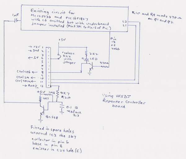
The general idea is to make use of a ‘WeathAlert’ receiver - see elsewhere on my site for a description. To this is added a password protected control system using one of my repeater boards as the foundation. Obviously this meant only a fraction of the PCB was used but it saved me manufacturing a new board and there were enough PCB lands to add some extra bits such as the third output, its LED and a simple audio amp.
The circuit consists of a MC145436 DTMF decoder chip into a PIC16F1827 running from its internal oscillator. Two of the control outputs make use of the existing PTT drivers although I have substituted 2N3643 transistors for the BC548 as they have a higher permissible current. The third transistor driver has been added using the vacant holes for the unused 4066.
Although the receiver has reasonable audio output in the vicinity of several hundred millivolts, the audio was badly unbalanced. Those of you who have experimented with DTMF will know that unless the low and high tones are close to equal amplitude the DTMF chip will struggle to decode. I put a double RC filter on the input to reduce the level of the higher DTMF tones and with the gain from the audio amp to make up for the loss of level due to the filters there is now plenty of adjustment available and reliable decoding from the MC145436. My new DSO earned its keep in fixing the levels.
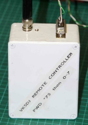
The whole system has been placed in a diecast box with a BNC socket for the antenna - in fact I’m using the original WeathAlert whip as it was designed for 148MHz use and should work well enough at the chosen 2M frequency.
The receiver is designed to work from 5-8 volts so I have powered it from the 78L05 on the controller board. The whole system draws 55mA at 12V when the LEDs are on and 29mA without.
Download the hex file with trial password and control details in a ZIP file. The password may be changed by altering the contents of EEDATA locations 0 and 1. Entry of 04 in location 00 and a 05 in location 01 will set the password as 45. As a * begins every password sequence then *457 would put all beacons on for this example.
*450 turns all off, *451 puts on 2M only, *452 puts on 70cm only, *454 puts 1296 beacon on. By adding the last digits you can setup any combination. E.g. *453 would put on 2M and 70cm or *456 would put on 70cm and 1296.
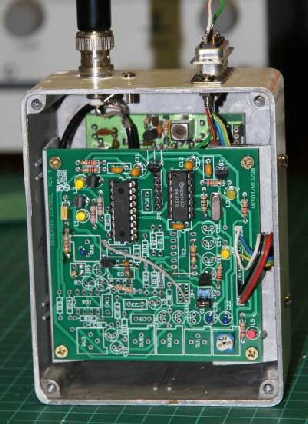
The left hand photo shows the general construction. The underneath board is the 2M receiver on 14X.XX MHz. It is salvaged from the WeathAlert device as described elsewhere on this site. The BNC antenna whip is also salvaged from WeathAlert.
The top board is the logic control making use of one of my repeater control boards with the DTMF decoder MC145436 and the 16F1827 doing the hard work.
Additional transistors can be seen at 3 o’clock - this is the simple audio amp making use of unused pins on those for the NE567, and at 4 o’clock the additional logic transistor built on the holes for the 4066.
The three LEDs are currently on to identify their places.
The DB15 has pins for earth (pin 1) and +12V (pin 8), 1296 control pin 5, 432 control pin 6, 144 control pin 7
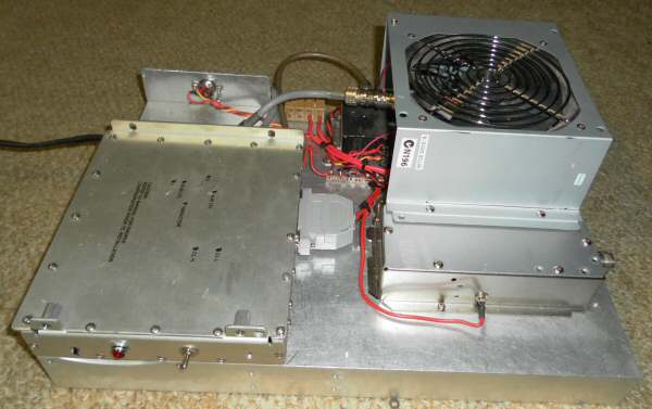
The new VK5RSE GPS locked beacons constructed by Col VK5DK.
To the front left is the main unit consisting of the GPS controlled oscillator and the driver stages for 2M, 70cm and 23cm. The GPS is mounted outside the beacon’s reinforced concrete ‘tank’. A front panel has been added since.
At the left rear is the DIN socket for the remote control interface. To the front right is the 70cm final while the black block at the rear is the 2M final stage. A fan is a precaution as the entire base is one large heat sink. We are hopeful that the previous summer heat problems will now disappear. The 1296 final is located elsewhere at the site.
| Repeater features |
| Solar version |
| 1750Hz decoder |
| Record and playback |
| Voice interface |
| Micor solution |
| Yagi Calculator |
| RD Contest logger |
| Moon Tracking |
| Orbitron interface |
| PRFCalc |
| TAIT programming |
| Proton Development Suite |
| Old crystals for radios |
| Compound interest |
| Yagi photos |
| Bird proofing |
| Bender |
| VK5DJ downloads |
| VK3UM downloads |
| Site map |